Image forming system

Inactive Publication Date: 2006-09-14
KONICA MINOLTA BUSINESS TECH INC
View PDF5 Cites 19 Cited by
  • Summary
  • Abstract
  • Description
  • Claims
  • Application Information

AI Technical Summary

Benefits of technology

[0017] Also, in the image forming system according to the present invention, preferably, when the post-processing apparatus is set in the first position, an upper surface of a cover of the post-processing apparatus serves as a guide for a long paper ejected from the image forming apparatus. This eliminates the necessity of separately providing a long paper guide member.
[0018] Additionally, it is preferred that when the post-processing apparatus is set in the first position, the upper surface

Problems solved by technology

However, there are cases in which printing on longer papers is required.
Conventionally, image forming apparatuses provided with post-processing apparatuses having functions as sorters, staplers or the like have a problem that a paper jam is likely to occur when a long paper is fed therein, and therefore such image forming apparatuses are constructed not to perform printing on long papers.
Thus, conventional image forming systems have been far away from meeting both of the demands for various functions by use of a post-processing apparatus and for printing on long papers by use of an image forming apparatus.
However, in order to enable printing on long papers in an image forming apparatus provided with a post-processing apparatus, the post-proces

Method used


Image

  • Image forming system
  • Image forming system
  • Image forming system

Examples


Example

[0044] An embodiment of an image forming system according to the present invention is described with reference to the accompanying drawings.

General Structure of Image Forming System; See FIGS. 1-6

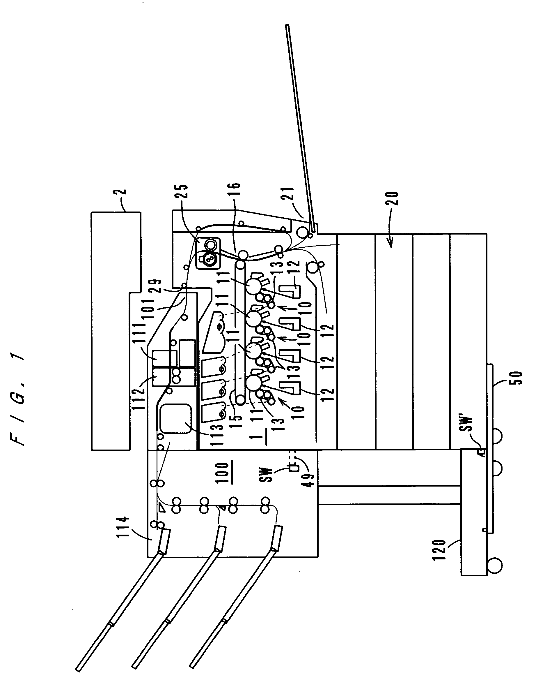
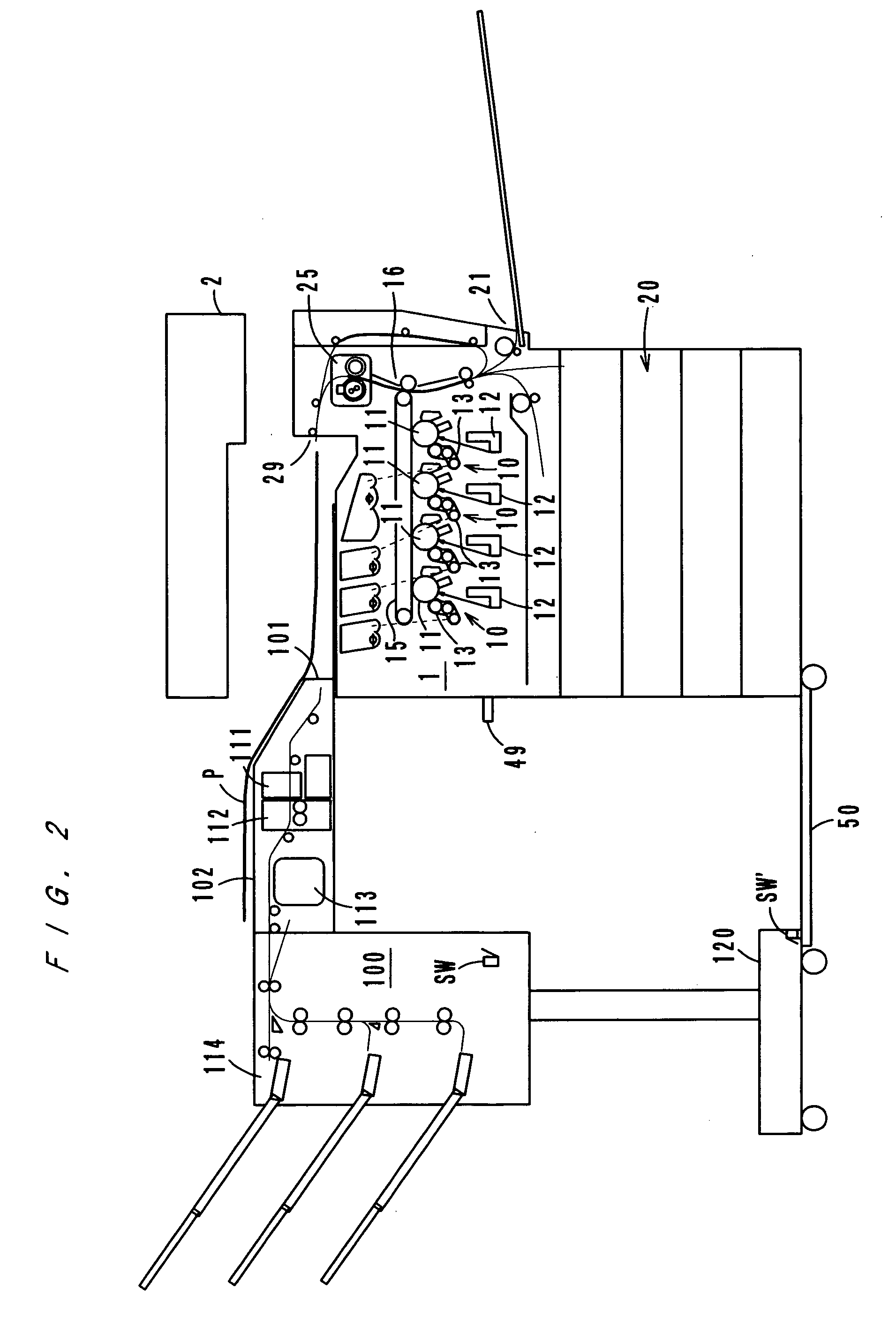
[0045] An image forming system shown by FIGS. 1 and 2 comprises an image forming apparatus 1 and a post-processing apparatus 100. FIG. 1 shows a state in which the post-processing apparatus 100 is set in a second position to receive non-long papers from the image forming apparatus 1. FIG. 2 shows a state in which the post-processing apparatus 100 is set in a first position to receive long papers from the image forming apparatus.

[0046] Here, non-long papers mean papers of sizes which are originally expected to be subjected to printing in the image forming apparatus 1, and long papers mean papers of longer sizes with respect to the paper feeding direction.

[0047] The post-processing apparatus 100 is movable horizontally along rails 50 from and to the image forming apparatus 1 so that a user...


PUM


Abstract

An image forming system having an image forming apparatus and a post-processing apparatus having a sorting function, a stapling function, etc. The post-processing apparatus is movable between a first position to receive long papers and a second position to receive non-long papers. When the post-processing apparatus is set in the second position, a paper inlet port of the post-processing apparatus faces a paper ejection port of the image forming apparatus.

Description

[0001] This application is based on a Japanese application No. 2005-64505 filed on Mar. 8, 2005, the content of which is incorporated by reference. BACKGROUND OF THE INVENTION [0002] 1. Field of the Invention [0003] The present invention relates to an image forming system, and more particularly to an image forming system comprising an image forming apparatus and a post-processing apparatus having a function as a sorter, a stapler or the like. [0004] 2. Description of Related Art [0005] Image forming apparatuses are generally structured to print images on papers of regular sizes, such as A4, A3, etc. However, there are cases in which printing on longer papers is required. [0006] Conventionally, image forming apparatuses provided with post-processing apparatuses having functions as sorters, staplers or the like have a problem that a paper jam is likely to occur when a long paper is fed therein, and therefore such image forming apparatuses are constructed not to perform printing on lon...

Claims


Application Information

Patent Timeline
IPC IPC(8): G03G15/00G03G21/00
CPCG03G15/6582G03G2215/00421G03G2215/00468G03G2221/1696G03G15/6552G03G15/6594G03G2221/1654
Inventor MAE, HIDEOOKUNISHI, KAZUOYAMADA, TATSUTOSHIKAWAI, ATSUSHIYOSHIZAKI, YOSHIHIKOYAMADA, KOU
Owner KONICA MINOLTA BUSINESS TECH INC
Why Eureka
Try Eureka