Engine control apparatus

Inactive Publication Date: 2007-05-01
MITSUBISHI ELECTRIC CORP
View PDF5 Cites 1 Cited by
  • Summary
  • Abstract
  • Description
  • Claims
  • Application Information

AI Technical Summary

Benefits of technology

[0011]An abnormality in the power supply voltage of the engine control apparatus according to the present invention is detected by comparing a power supply voltage of the engine control apparatus with a power supply voltage of a different power supply w

Problems solved by technology

When the output voltage of the generator has risen above an abnormally high voltage value, the field current is shut off to forcedly stop the power generation.
However, the aforementioned protection against overcharge has the following problem.

Method used


Image

  • Engine control apparatus
  • Engine control apparatus
  • Engine control apparatus

Examples


first embodiment

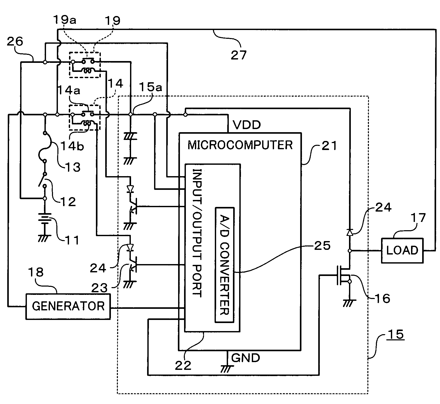
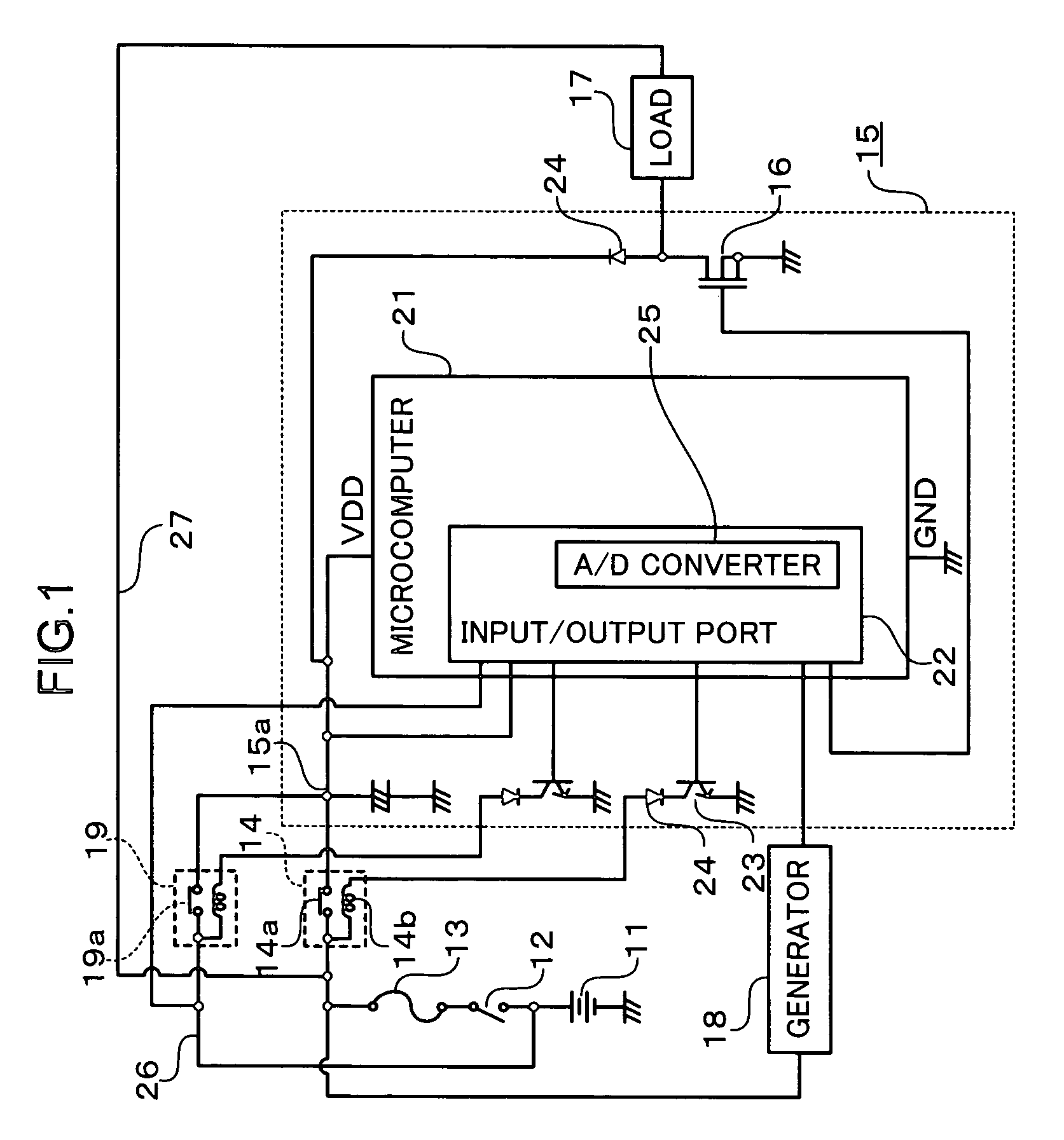
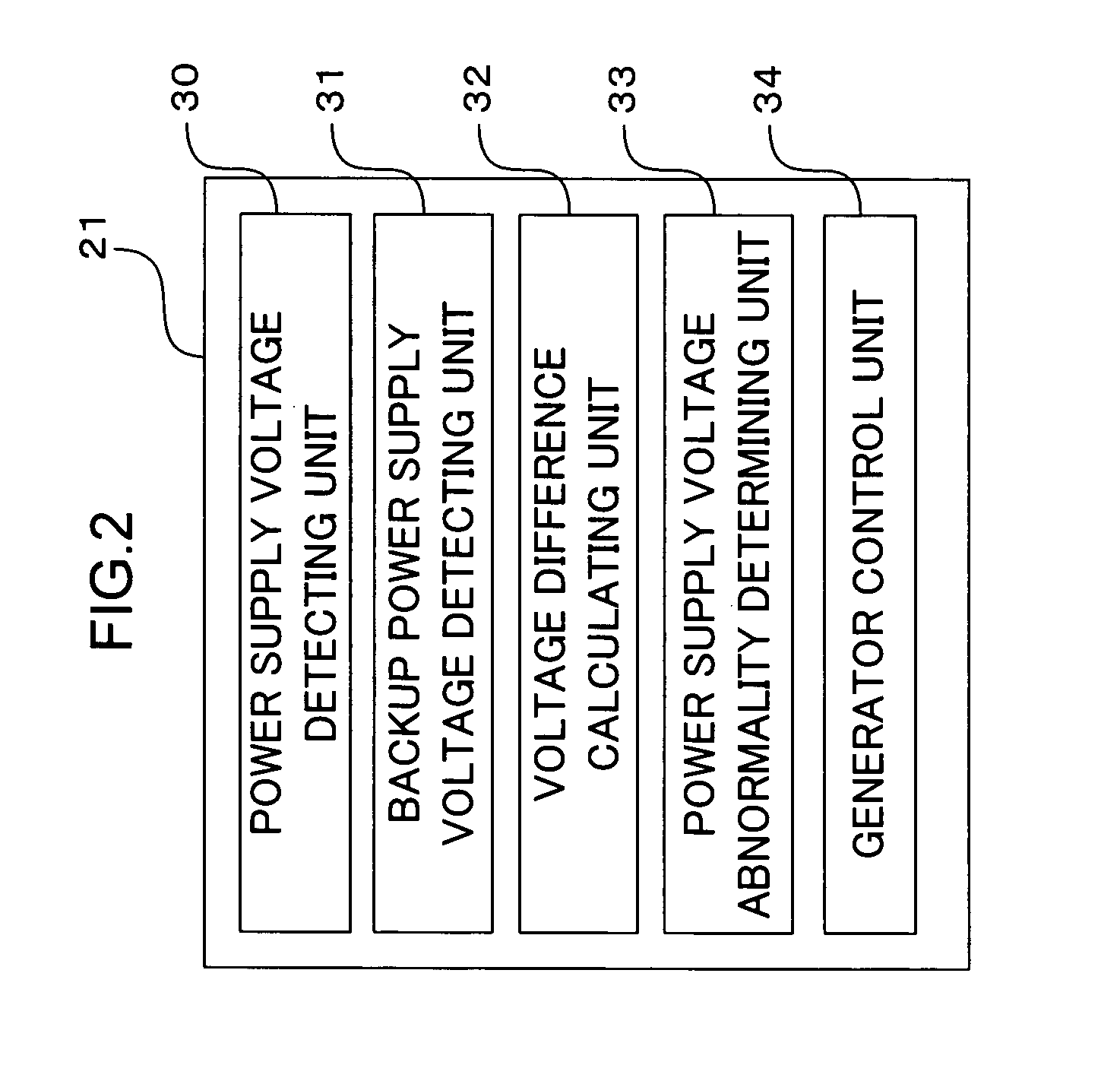
[0024]FIG. 1 is a schematic diagram of an engine control apparatus according to the first embodiment of the present invention. FIG. 2 is a functional block diagram of a microcomputer according to the first embodiment of the present invention. FIG. 3 is a flowchart showing a power supply voltage abnormality detecting routine executed in the engine control apparatus according to the first embodiment of the present invention. FIG. 4 is a flowchart showing a power generation control processing routine executed in the engine control apparatus according to the first embodiment of the present invention.

[0025]An engine control apparatus 15 according to the first embodiment of the present invention drives a load 17 related to operation of an engine (not shown). The engine control apparatus 15 controls the charge / discharge of a battery 11, which supplies the engine control apparatus 15 and the load 17 with power.

[0026]The battery 11 is connected to a power supply line 15a of the engine contro...

second embodiment

[0050]FIG. 5 is a functional block diagram of a microcomputer according to the second embodiment of the present invention. FIG. 6 is a flowchart showing a power supply voltage abnormality detecting routine executed in an engine control apparatus according to the second embodiment of the present invention.

[0051]The engine control apparatus according to the second embodiment of the present invention is different from the engine control apparatus according to the first embodiment of the present invention in that a power supply voltage for the load is used as a value to be compared with the power supply voltage instead of the backup power supply voltage. Since they are identical to each other in other respects, the description of identical parts will be omitted by assigning thereto the same symbols as in the first embodiment of the present invention.

[0052]A microcomputer 21B according to the second embodiment of the present invention is different from the microcomputer 21 according to t...

third embodiment

[0065]FIG. 7 is a functional block diagram of a microcomputer according to the third embodiment of the present invention. FIG. 6 is a flowchart showing a power supply voltage abnormality detecting routine executed in an engine control apparatus according to the second embodiment of the present invention.

[0066]The engine control apparatus according to the first embodiment of the present invention is different from the engine control apparatus according to the first embodiment of the present invention in that a power supply voltage for the load is used as a value to be compared with the power supply voltage instead of the backup power supply voltage. Since they are identical to each other in other respects, the description of identical parts will be omitted by assigning thereto the same symbols as in the first embodiment of the present invention.

[0067]A microcomputer 21C according to the third embodiment of the present invention is different from the microcomputer 21 according to the ...


PUM


Abstract

It is an object of the present invention to provide an engine control apparatus for detecting a voltage abnormality caused in a power supply thereof at low cost. An engine control apparatus for controlling an engine, includes: power supply voltage detecting unit for detecting a power supply voltage of a battery mounted on a vehicle as a power supply, which supplies the engine control apparatus with power; backup power supply voltage detecting unit for detecting a backup power supply voltage of a backup power supply, which supplies the engine control apparatus with power from the battery via a different path; voltage difference calculating unit for calculating a voltage difference between the power supply voltage and the backup power supply voltage; and power supply voltage abnormality determining unit for determining that there is an abnormality in the power supply voltage when the voltage difference is not within a predetermined range.

Description

BACKGROUND OF THE INVENTION[0001]1. Field of the Invention[0002]The present invention relates to an apparatus for controlling an engine, capable of detecting an abnormality in a power supply voltage supplied thereto.[0003]2. Description of the Related Art[0004]An apparatus for controlling an engine is supplied with power from a battery. The battery is charged by a generator mounted on a vehicle. The generator generates power when a field coil is excited with a field current and a power generation current is caused to flow through an armature coil rotating through rotation of the engine. Power generation control of the generator is performed by feedback control. That is, a control transistor is operated to be turned on and off to excite the field coil so that the voltage of the battery charged by the generator is held at a target voltage, and a target amount of power for making a voltage difference into zero is generated. The battery is charged through the power generation current, a...

Claims


Application Information

Patent Timeline
IPC IPC(8): H02J7/14G06F19/00F02D29/06F02D45/00
CPCH02J7/166H02J7/16H02J7/00302H02J7/0047
Inventor SHIMADA, NAOKISAKAIGAKI, KEIICHIRONISHIMOTO, KOJI
Owner MITSUBISHI ELECTRIC CORP
Why Eureka
Try Eureka