This helps you quickly interpret patents by identifying the three key elements:
Problems solved by technology
Method used
Benefits of technology
[0013] the present invention has been made in view of the above circumstances and provides an image forming apparatus, which may prevent defects in image quality, such as low den
Problems solved by technology
However, the above-described techniques have the following problems.
However, as described above, it is difficult to prevent the cleaning additive from being accumulated in the developer of the developing device during reclaim.
Therefore, if the amount of the metal stearate, which serves as a cleaning additive and is added to a
Method used
Image
Click on the blue label to locate the original text in one second.
Reading with bidirectional positioning of images and text.
Examples
first embodiment
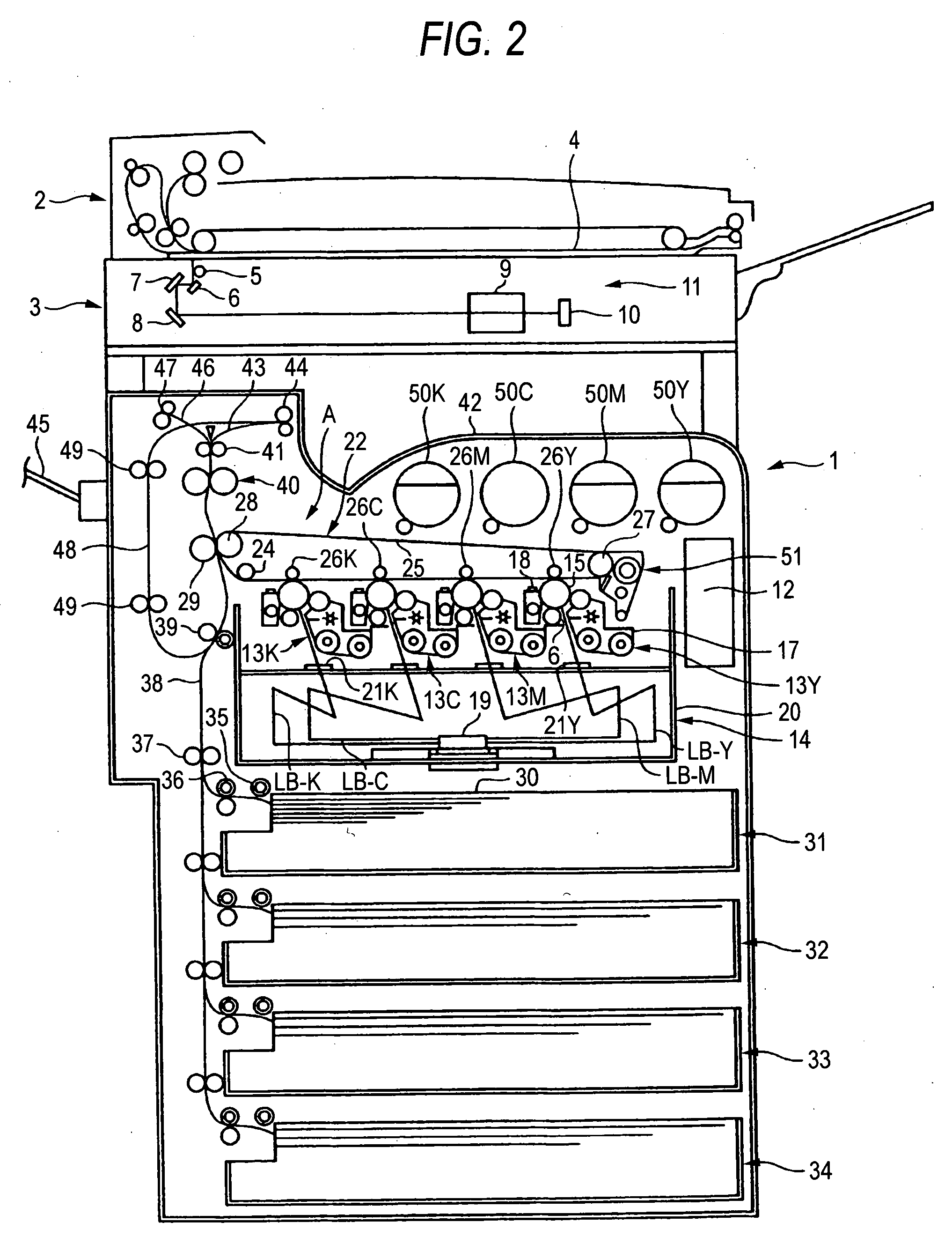
[0021]FIG. 2 is a diagram showing a structure of a color multifunction machine serving as an image forming apparatus according to a first embodiment of the invention. The color multifunction machine has all functions of a copier, a printer, and a facsimile.
[0022] As shown in FIG. 2, the color multifunction machine has a scanner 2 on an upper portion thereof as an image-scanning device, and is connected to a personal computer (not shown) through a network (not shown).
[0023] The color multifunction machine functions as a copier for copying an image of a document scanned by the scanner, a printer for printing an image on the basis of image data transmitted from the personal computer, and a fax for transmitting or receiving image data over telephone lines.
[0024] In FIG. 2, reference numeral 1 denotes a main body of the color multifunction machine. An automatic document feeder (ADF) 2 for automatically feeding documents (not shown) one by one and an image input terminal (IIT) 3 for sc...
second embodiment
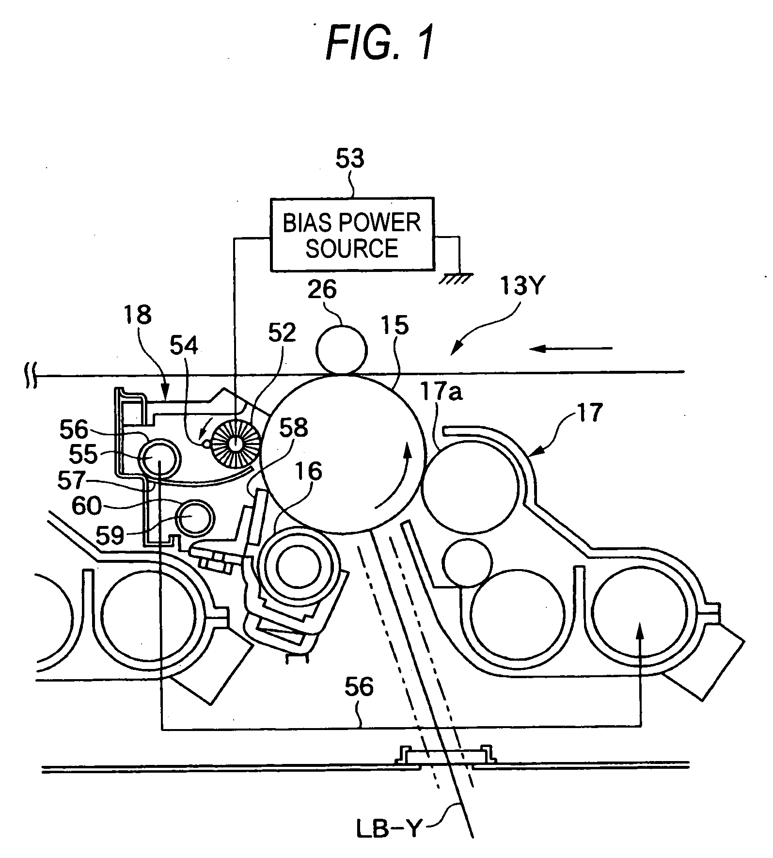
[0066]FIG. 4 is a diagram showing a second embodiment of the invention. In FIG. 4, the same parts as those in the first embodiment are indicated by the same reference numerals. In the second embodiment, the invention is applied to not a full color image forming apparatus, but a monochrome image forming apparatus.
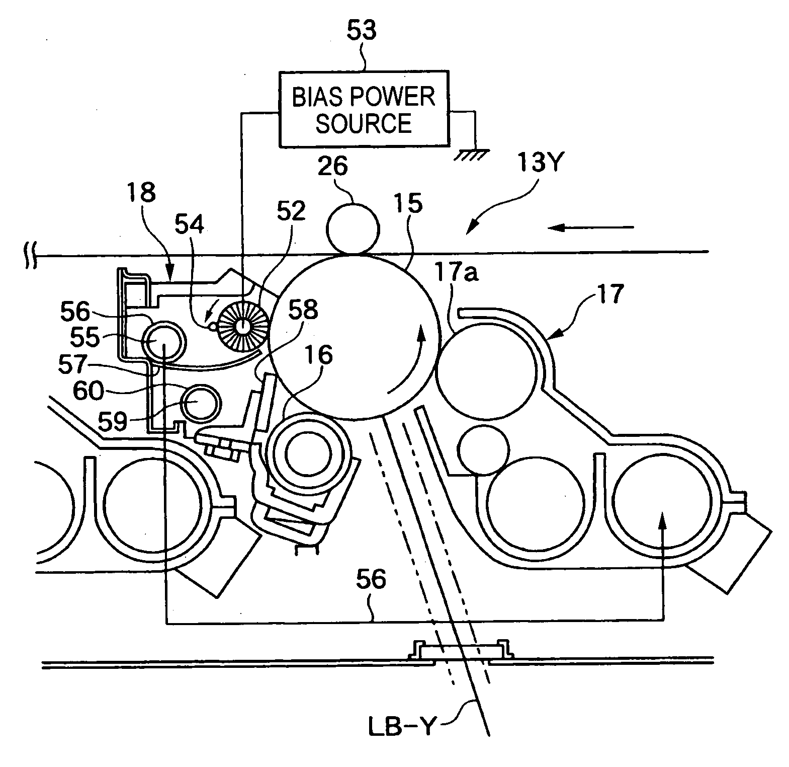
[0067] That is, as shown in FIG. 4, the image forming apparatus according to the second embodiment includes a single photoconductor drum 15. A primary charging device 16, an exposure device 14, a developing device 17, a transfer roller 26, and a cleaning device 18 are arranged around the photoconductor drum 15 along the rotation direction of the photoconductor drum 15. In addition, a sheet 30 is fed from a lower side to an upper side along the side surface of the photoconductor drum 15.
[0068] Furthermore, as shown in FIG. 4, the cleaning device 18 is disposed above the photoconductor drum 15 in the image forming apparatus. The cleaning device 18 includes a conductive brush...
PUM
Abstract
An image forming apparatus includes an image carrier, a cleaning device and a developing device. The cleaning device recovers a toner remaining on the image carrier. The toner recovered by the cleaning device is supplied to the developing device. The cleaning device includes a conductive brush member and an elastic blade. The conductive brush member is disposed on upstream of the image carrier in a rotation direction of the image carrier so as to be in contact with the image carrier. The conductive brush member recovers the toner remaining on the image carrier electrostatically. The elastic blade is disposed on downstream of the image carrier so as to be in contact with the image carrier. A toner recovered by the conductive brush member is supplied to the developing device and used in image formation again. A toner recovered by the elastic blade is discarded.
Description
BACKGROUND OF THE INVENTION [0001] 1. Field of the Invention [0002] The present invention relates to an image forming apparatus using an electrophotographic method, such as a copier, printer, or facsimile, and more particularly, to an image forming apparatus that reuses (reclaim) a toner recovered by a cleaning device in image formation. [0003] 2. Description of the Related Art [0004] There is an related art that discloses an image forming apparatus using an electrophotographic method, (such as a copier, printer, or facsimile), in which a toner recovered by a cleaning device is reused (reclaimed) to form an image. [0005] A cleaning device disclosed above is disposed adjacent to a rotatable image carrier to remove a toner remaining on the image carrier after transferring. The cleaning device includes an elastic blade abutting against the image carrier, a rotatable mixing transfer member, a first toner recovering member and a second toner recovering member. The rotatable mixing convey...
Claims
Application Information
Patent Timeline
Application Date:The date an application was filed.
Publication Date:The date a patent or application was officially published.
First Publication Date:The earliest publication date of a patent with the same application number.
Issue Date:Publication date of the patent grant document.
PCT Entry Date:The Entry date of PCT National Phase.
Estimated Expiry Date:The statutory expiry date of a patent right according to the Patent Law, and it is the longest term of protection that the patent right can achieve without the termination of the patent right due to other reasons(Term extension factor has been taken into account ).
Invalid Date:Actual expiry date is based on effective date or publication date of legal transaction data of invalid patent.