Fastener, roofing system and method

a technology of fasteners and roofing systems, applied in the direction of threaded fasteners, screwdrivers, mechanical equipment, etc., can solve the problems of membrane to wrinkle or pinch around the plate, membrane to wrinkle or pinch around the fastener, and the fastener is inclined to strip out of the roof deck, so as to improve the resistance to wind uplift forces and reduce labor. , the effect of improving the durability

Inactive Publication Date: 2006-09-21
BFS DIVERSIFIED PRODS
View PDF25 Cites 20 Cited by
  • Summary
  • Abstract
  • Description
  • Claims
  • Application Information

AI Technical Summary

Benefits of technology

[0013] A benefit of the present invention resides in the ability to provide a single-ply membrane roofing system having an improved fastener which does not compromise the integrity of the membrane during installation.
[0014] Another benefit of the invention relates to a single-ply membrane roofing system having improved durability under a wide range of climatic conditions and improved resistance to wind uplift forces.
[0015] Still another benefit of the invention is associated with eliminating anchor plates which reduces a substantial amount of the labor normally performed on the roof deck, thereby increasing efficiency and reducing labor costs.
[0016] Yet another benefit of the present invention is to provide a method of installing a single-ply membrane roof to a roof deck that is simple and economical.

Problems solved by technology

A problem with many presently available anchor plates is that an edge of the plate can contact the membrane during installation and cause the membrane to wrinkle or pinch around the plate.
Similar to the problems associated with the anchor plates, the head of the fastener can also contact the membrane and cause the membrane to wrinkle or pinch around the fastener.
However, known fasteners are inclined to strip out of the roof deck when installed in this manner.
If the membrane is pinched, the membrane may tear thereby making the roofing system susceptible to water damage and / or wind uplift forces.
Further, because the anchor plates and fasteners are not installed flush with the first layer, the membrane can be damaged by hail.

Method used


Image

  • Fastener, roofing system and method
  • Fastener, roofing system and method
  • Fastener, roofing system and method

Examples


Embodiment Construction

[0022] It should, of course, be understood that the description and drawings herein are merely illustrative and that various modifications and changes can be made in the structures disclosed without departing from the spirit of the invention. Like numerals refer to like parts throughout the several views.

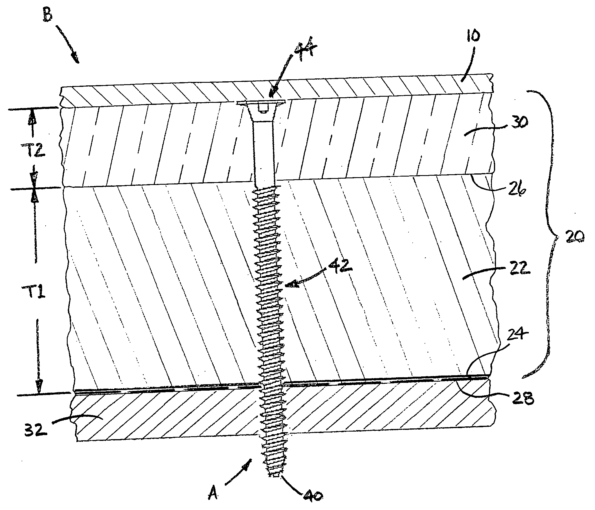
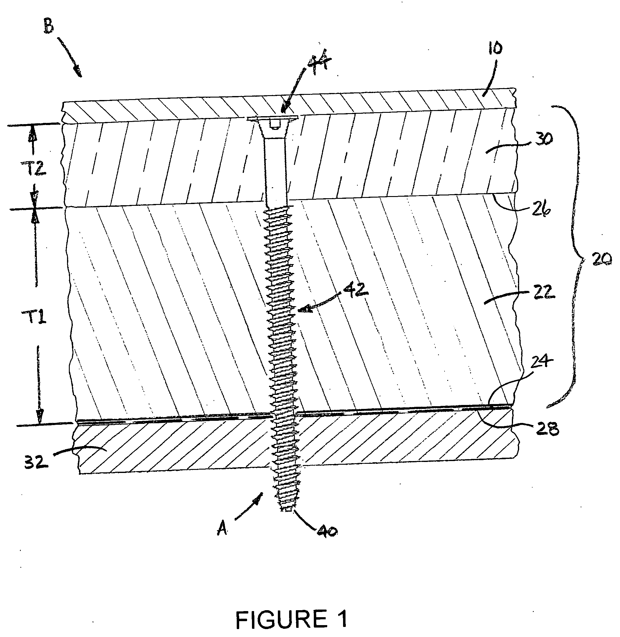
[0023] Referring now to the drawings, wherein the showings illustrate an embodiment of the invention only and are not intended to limit same, FIGS. 1-3 show a penetrating fastener A for a roofing system B. Roofing system B typically includes a flexible waterproof roof membrane 10, generally a single sheet of synthetic, flexible polymer material designed for long term waterproofing performance. Preferably, the roof membrane is an ethylene propylene diene rubber (EPDM) or thermoplastic polyolefin (TPO), however, other synthetic polymers can be used for the roof membrane without departing from the scope and intent of the present invention.

[0024] The roof membrane sealingly engages a ...


PUM


Abstract

The present disclosure relates to a penetrating fastener for a roofing system having a flexible waterproof membrane adhesively attached to an upper layer which is fastened to a roof deck. The fastener is dimensioned to extend through the upper layer and threadingly engage the lower roof deck. The fastener includes a self-drilling tip for piercing the upper layer and the roof deck and a self-tapping threaded shank portion located above the tip. An unthreaded shank portion is located adjacent the threaded shank portion. A tapered collar is located above the unthreaded shank portion. The fastener further includes a driving head which has a flange extending at an angle from a first side of the head to the tapered collar for reducing the tensile forces associated with the head being installed flush with or slightly below the upper layer. The unthreaded shank portion, tapered collar and driving head together form an unthreaded length of the penetrating fastener that is at least as great as a thickness of a portion of the upper layer. A method includes attaching a roofing system using the penetrating fasteners.

Description

[0001] This application claims priority from U.S. Provisional Patent Application No. 60 / 663,064, filed on Mar. 18, 2005, which is hereby incorporated herein by reference in its entirety.BACKGROUND OF THE INVENTION [0002] The present invention generally relates to membrane roofing systems, and, more particularly, to a penetrating fastener for securing a first or upper layer of a roofing system to a roof deck and a roofing system including such fasteners. The invention further relates to methods of securing the first or upper layer to the roof deck and of attaching a membrane to the first layer in such a manner that the membrane is not compromised by the fastener. [0003] A roof deck may be constructed from plywood, metal decking, concrete or any other suitable material. In certain roofing installations for commercial buildings, a first layer is secured to the roof deck. The first layer generally includes a lower thermal performance section, such as a layer of insulation, for example, ...

Claims


Application Information

Patent Timeline
Patent Type & Authority Applications(United States)
IPC IPC(8): E04B5/00
CPCE04D3/3603E04D5/143E04D5/145F16B25/0031F16B25/103F16B25/106F16B35/06F16B35/065
Inventor WASITIS, WILLIAM A.JANNASCH, JAMES A.
Owner BFS DIVERSIFIED PRODS
Why Eureka
Try Eureka