Electrical connector with improved fastener

a technology of electric connectors and fasteners, which is applied in the direction of fastening means, coupling device connections, mechanical instruments, etc., can solve the problems of difficult riveting of the riveting portion to abut against the shell in manufacture, and the appearance of the electrical connector is not good enough, so as to achieve the effect of easy assembly

Active Publication Date: 2009-04-14
HON HAI PRECISION IND CO LTD
View PDF5 Cites 9 Cited by
  • Summary
  • Abstract
  • Description
  • Claims
  • Application Information

AI Technical Summary

Benefits of technology

[0006]A main object of the present invention is to provide an electrical connector with improved fastener for easy assembly thereof.
[0007]In order to attain the object above, an electrical connector includes an insulative housing, a plurality of contacts retained in the insulative housing, a metal shell partially enclosing the insulative housing, a pair of board locks and a pair of fasteners for assembling the board locks and the shell onto the insulative housing. The insulative housing defines a pair of apertures on lateral sides thereof. The shell defines a pair of through holes corresponding to the apertures. Each board lock defines a bore therethrough corresponding to the aperture. The through holes and the bores are positioned on opposite sides of the apertures for the fasteners extending therethrough. Each fastener extends through the through hole and through the aperture and the bore, and comprises a resisting portion abutting against the shell and a rivet portion extending beyond the bore. The rivet portion is hollow to form a recess therein and defines a plurality of notches in communication with the recess to separate the rivet portion into several discontinuous parts. When in riveted process, the discontinuous parts of the rivet portion are easy to be riveted to abut against corresponding board lock, thereby facilitating the manufacture of the electrical connector and improving the appearance of the electrical connector as well.

Problems solved by technology

However, since the rivet portion is continuous along its circumference, the rivet portion is avulsed difficultly to riveted to abut against the shell in manufacture.
Besides, under the riveted process, the avulsion of the continuous rivet portion might be anomalous so that the appearance of the electrical connector is not good enough.

Method used


Image

  • Electrical connector with improved fastener
  • Electrical connector with improved fastener
  • Electrical connector with improved fastener

Examples


Embodiment Construction

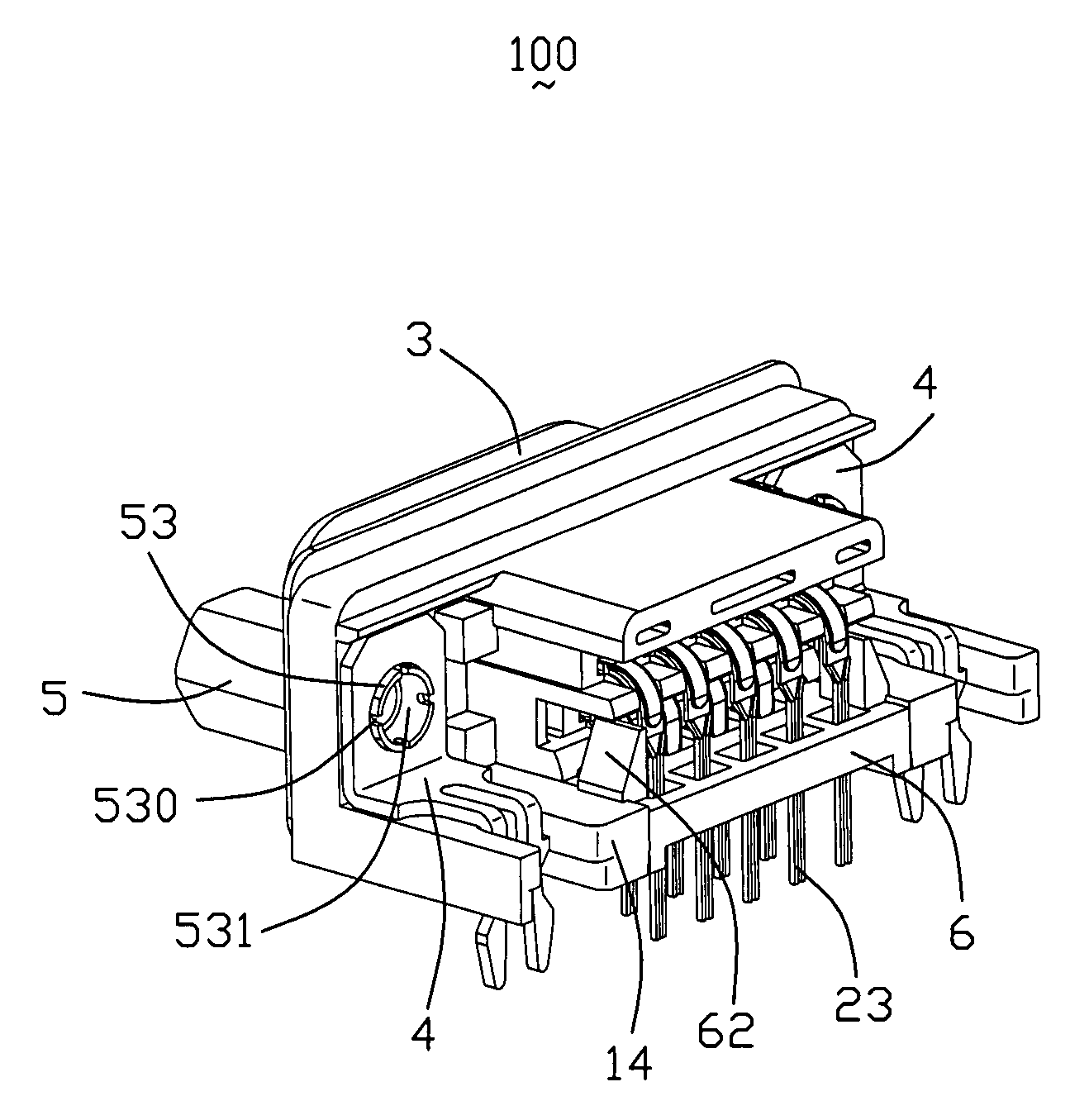
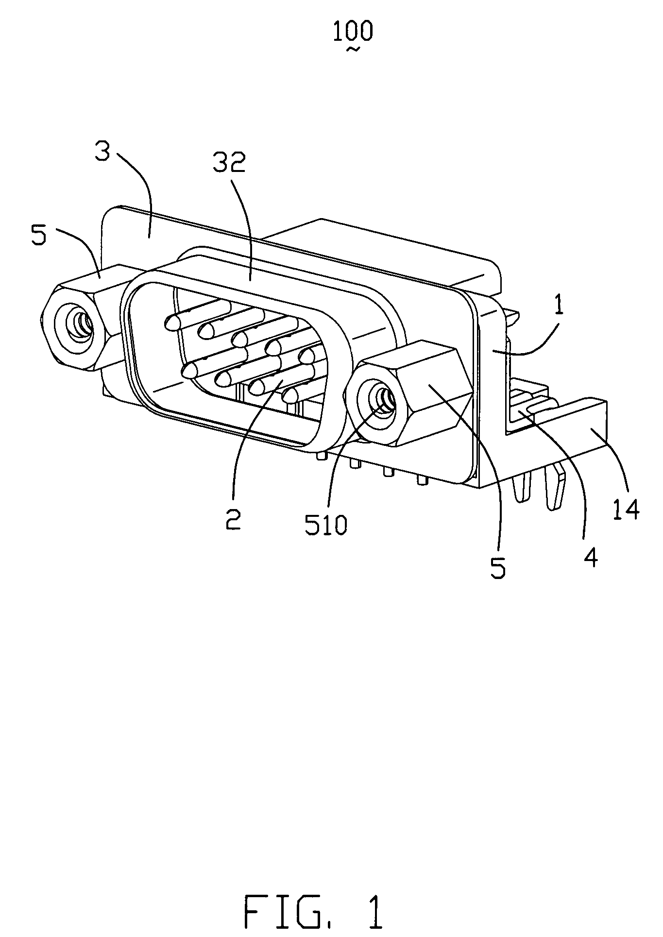
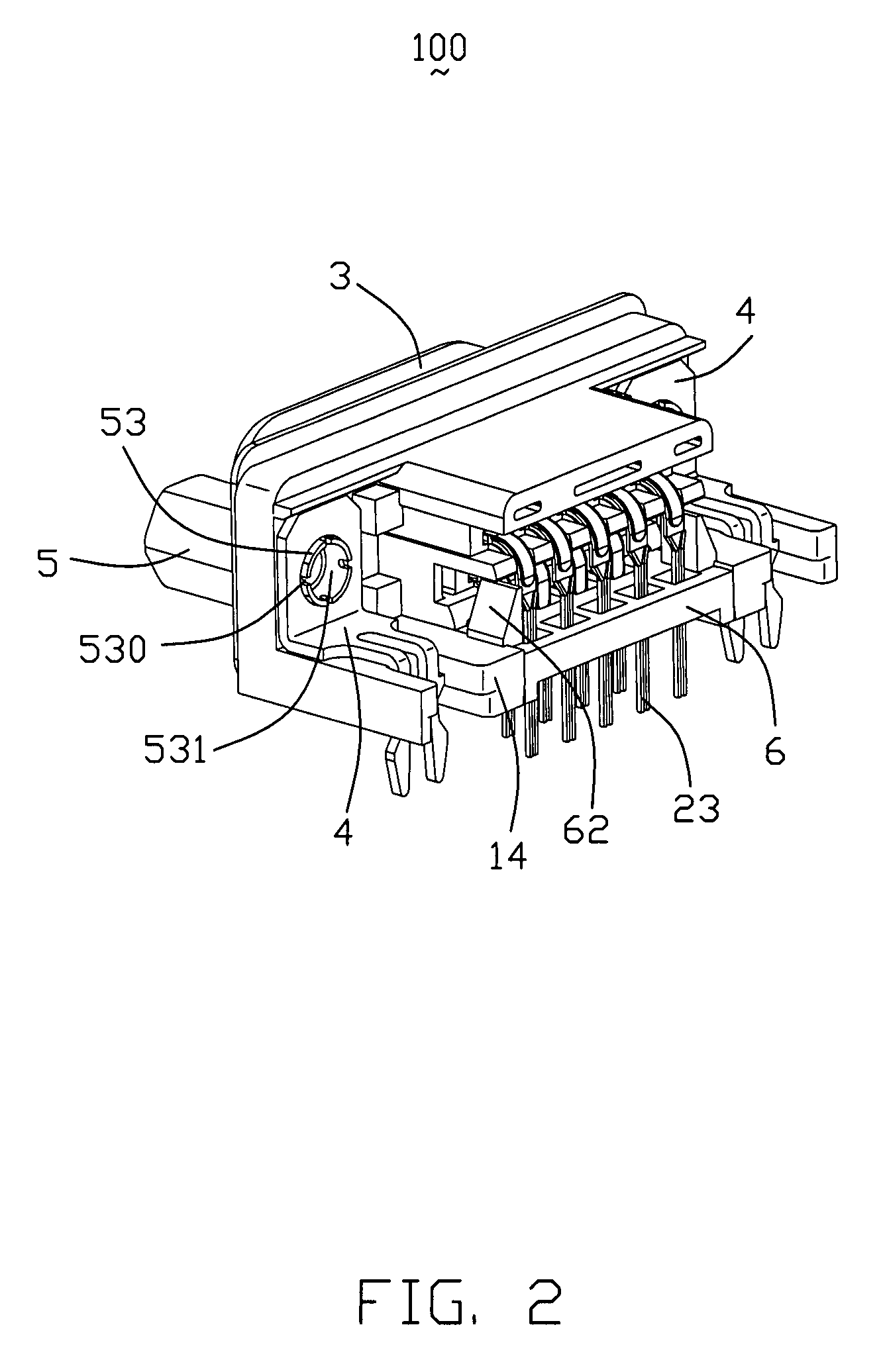
[0015]Referring to FIGS. 1-5, an electrical connector 100 includes an insulative housing 1, a plurality of contacts 2 retained in the insulative housing 1, a metal shell 3 partially enclosing the insulative housing 1, a pair of board locks 4 and a pair of fasteners 5 for assembling the board locks 4 and the metal shell 3 onto the insulative housing 1.

[0016]Referring to FIGS. 4-5, the insulative housing 1 comprises a flat front surface 10, a rear surface 11 opposite to the front surface 10 and a plurality of passageways 12 extending through the front and rear surfaces 10, 11 for receiving the contacts 2. A pair of polygonal apertures 13 are defined therethrough on lateral sides of the insulative housing 1. A pair of mounting protrusions 14 extend from a bottom edge of the insulative housing 1 for mounting the electrical connector 100 to a PCB (not shown).

[0017]The contacts 2 are assembled from the rear surface 11 to the insulative housing 1. Each contact 2 comprises a retaining porti...


PUM


Abstract

An electrical connector (100) includes an insulative housing (1), a plurality of contacts (2) retained in the insulative housing (1), a metal shell (3) partially enclosing the insulative housing, a pair of board locks (4) and a pair of fasteners (5) for assembling the board locks (4) and the metal shell (3) onto the insulative housing. The fastener (5) includes a resisting portion (51) abutting against the metal shell and a rivet portion (53) extending through the board lock. The rivet portion (53) is hollow to form a recess (531) therein and defines a plurality of notches (530) to separate the rivet portion (53) into several discontinuous parts which is riveted to abut against the board lock.

Description

BACKGROUND OF THE INVENTION[0001]1. Field of the Invention[0002]The present invention relates to an electrical connector, and more particularly to an electrical connector with improved fastener.[0003]2. Description of the Prior Art[0004]U.S. Pat. No. 6,679,727 B1 discloses a conventional electrical connector which comprises an insulative housing, a plurality of terminals received in the insulative housing, a shell partially enclosing the housing, a pair of board locks and a pair of fasteners for assembling the board locks onto the housing. Each fastener has a base plate and a hollow cylinder extending from the base plate. The hollow cylinder extends through a through hole of the board lock with the base plate to abut against the board lock on a rear side of the insulative housing. The hollow cylinder further comprises a rivet portion on a distal end thereof. The rivet portion is stamped outwardly to riveted to abut against a front surface of the shell on a front side of the insulati...

Claims


Application Information

Patent Timeline
Patent Type & Authority Patents(United States)
IPC IPC(8): H01R12/20H01R12/71
CPCH01R13/6215H01R12/7029H01R12/727
Inventor XIANG, XING-HAI
Owner HON HAI PRECISION IND CO LTD
Why Eureka
Try Eureka