Disk casing

a technology for disc casings and casings, applied in the field of disk casings, can solve the problems of hard storage of disk casings employing the structure, deterioration of productivity when molding disk casings, type disk casings, etc., and achieve the effect of preventing the breakage of the end portion due to a large deflection

Inactive Publication Date: 2006-09-21
FUJIFILM HLDG CORP +1
View PDF6 Cites 10 Cited by
  • Summary
  • Abstract
  • Description
  • Claims
  • Application Information

AI Technical Summary

Benefits of technology

[0011] In view of the foregoing observations and description, the primary object of the present invention is to provide a disk casing in which the visibility of what is recorded on the backbone of the lower index card is improved without changing the outer contour of the disk casing.
[0017] In accordance with the present invention, since the end wall of the lower lid on the side of the opening-and-closing axis is formed to be substantially flush with the upper surface of the end portion of the disk tray so that the upper edge portion thereof is opposed to an outer edge portion of the end portion of the disk tray by way of a slit, and the upper end of the lower index card is inserted into the slit, the height of the backbone of the lower index card, which has been 6 mm or so in the conventional 10 mm thick disk casing, can be 8 to 9 mm, and the visibility of what is recorded on the backbone of the lower index card can be extremely improved especially when a number of disk casings are stacked or are accommodated in a rack in an arranged state.
[0018] Further, when the surface of the outer edge portion of the end portion of the disk tray which faces the slit is a slant surface or an arcuate surface which increases downward the width of the slit, the outer edge portion of the end portion becomes less apt to engage with the backbone of the lower index card during assembly of the disk casing.
[0019] Further, when a support leg having a lower end which can contact with the lower index card on the inner bottom surface of the lower lid is provided on a lower surface of the end portion of the disk tray to be suspended therefrom, the lower end of the support leg is borne by the inner bottom surface of the lower lid by way of the lower index card when a number of disk casings are stacked or the end portion of the disk tray is applied with load, whereby breakage of the end portion due to a large deflection thereof can be prevented and at the same time, lift of an end portion of the lower index card to cause the backbone thereof to bulge outside the slit is prevented.

Problems solved by technology

However, this structure is disadvantageous in that the outer contour of the disk casing must be changed, and at the same time, the disk casings employing the structure are harder to store as compared with other standard type disk casings.
Further, the part of the disk casing in the form of the convex lens deteriorates the productivity when molding the disk casing.

Method used


Image

  • Disk casing
  • Disk casing
  • Disk casing

Examples


Embodiment Construction

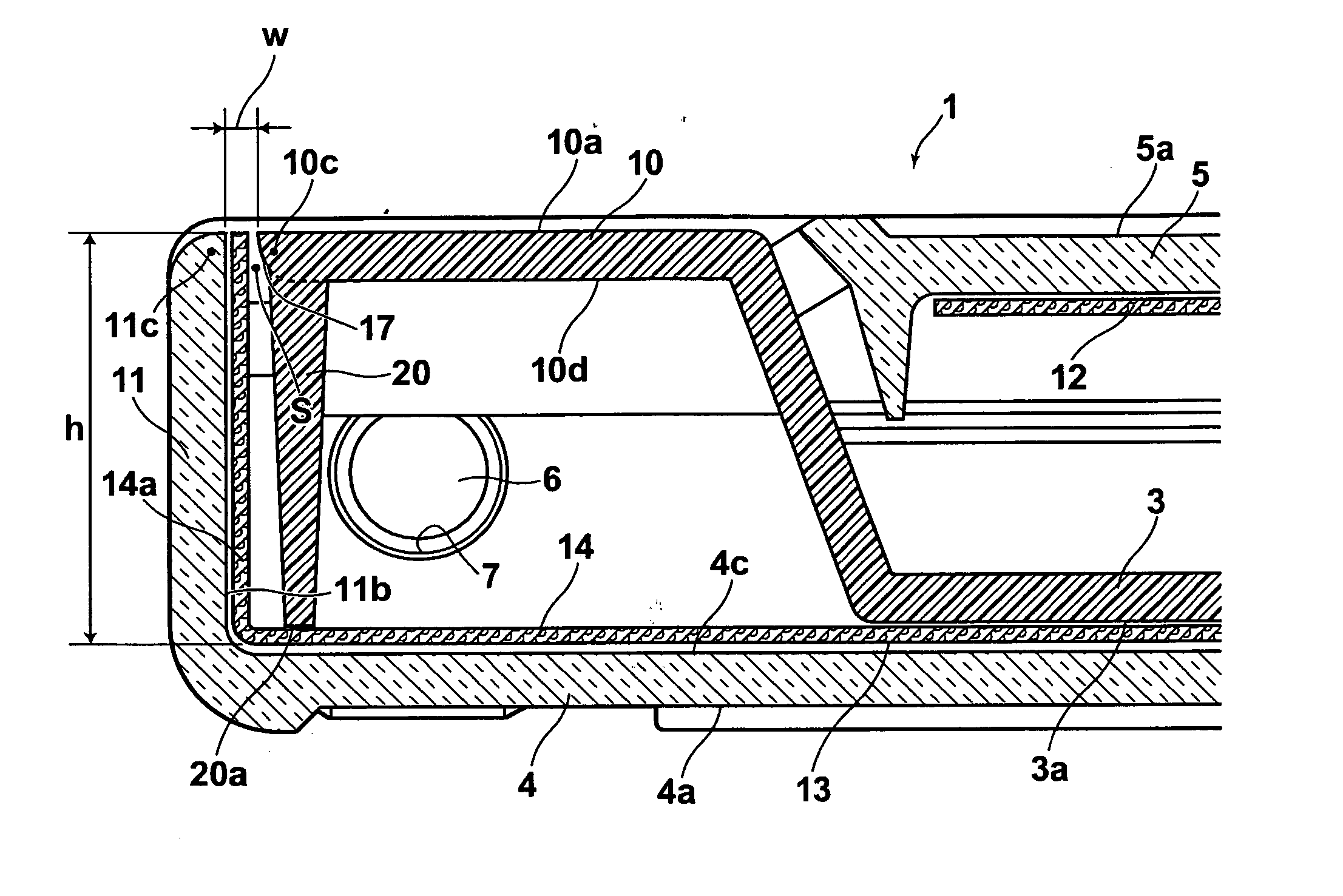
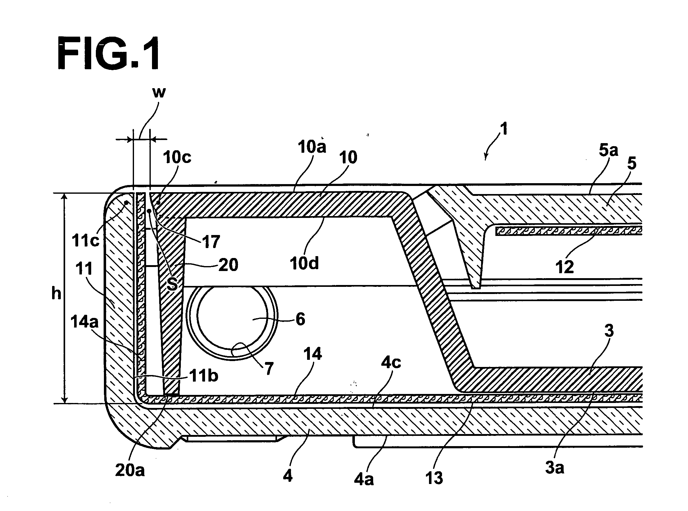
[0023] In FIG. 1, elements analogous to those in FIG. 3 will be given the same reference numerals and will not be described here.

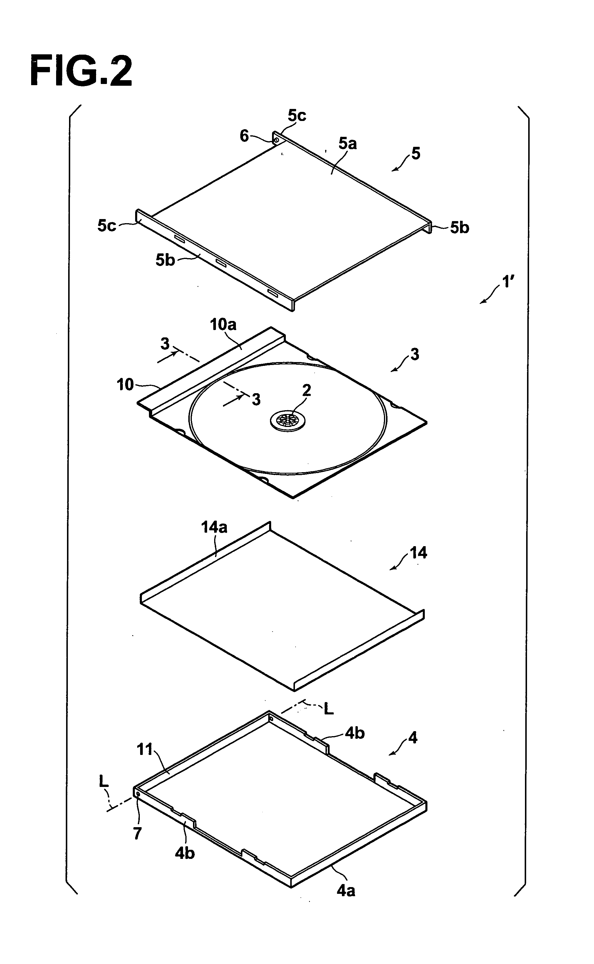
[0024] In FIG. 1, in a disk casing 1 in accordance with an embodiment of the present invention, as the conventional disk casing 1′ shown in FIG. 3, a disk tray 3 is provided with an elongated end portion 10 having an upper surface 10a facing upward substantially flush with the principal surface 5a of the upper lid 5 when the casing 1 is closed and adjacently to the principal surface 5a. However, in the disk casing 1 of this embodiment, the end portion 10 of the disk tray 3 is narrower in the horizontal width (lateral width in FIG. 1) than in the conventional disk casing 1′ so that its outer edge portion 10c is positioned inside the end wall 11 of the lower lid 4 on the side of the axis L.

[0025] On the other hand, the end wall 11 of the lower lid 4 is formed high so that its outer edge portion 11c is positioned substantially flush with the upper surface 1...


PUM

PropertyMeasurementUnit
thicknessaaaaaaaaaa
heightaaaaaaaaaa
heightaaaaaaaaaa

Abstract

The disk tray of a disk casing is provided with an end portion which has an upper surface facing upward flush with a principal surface of the upper lid when the casing is closed, and an end portion of a lower index card inserted in a space between the disk tray and the lower lid is bent upward along an inner surface of the end wall of the lower lid on the side of the axis. The end wall of the lower lid on the side of the axis is formed to be flush with the upper surface of the end portion of the disk tray so that the upper end of the lower index card is inserted into the slit by way of which the upper edge portion is opposed to an outer edge portion of the end portion of the disk tray.

Description

BACKGROUND OF THE INVENTION [0001] 1. Field of the Invention [0002] This invention relates to a disk casing, and more particularly to a disk casing for accommodating a recording medium such as a CD or a DVD. [0003] 2. Description of the Related Art [0004] As shown in FIG. 2, a three-piece disk casing 1′ which is 10 mm in thickness and has been commonly used comprises a plastic disk tray 3 having at a central portion of an upper surface thereof a disk damper 2 which is engaged with a central opening of a disk (not shown) to removably support the disk, a transparent plastic lower lid 4 which has a flat principal surface (a flat outer surface having a wide area) 4a to removably accommodate and fix the disk tray 3, and a transparent plastic upper lid 5 which has a flat principal surface 5a and is pivoted on the lower lid 4 to be opened and closed about an axis L with respect to the lower lid 4. [0005] The upper lid 5 has a pair of side walls 5b and pair of hinge arms 5c which are extens...

Claims


Application Information

Patent Timeline
Patent Type & Authority Applications(United States)
IPC IPC(8): B65D85/30B65D71/00
CPCG11B33/0427
Inventor SHIGA, HIDEAKI
Owner FUJIFILM HLDG CORP
Why Eureka
Try Eureka