Inverter unit for vehicle

a technology for inverter units and vehicles, applied in the direction of dynamo-electric converter control, dc-ac conversion without reversal, propulsion by batteries/cells, etc., can solve the problems of increasing the size and manufacturing cost of vehicles, and achieve the effect of effectively arranging each inverter circuit module, reducing the overall size of components and vehicles, and reducing impedan

Inactive Publication Date: 2006-09-21
TOYOTA JIDOSHA KK +1
View PDF0 Cites 204 Cited by
  • Summary
  • Abstract
  • Description
  • Claims
  • Application Information

AI Technical Summary

Benefits of technology

The technical effect of this patent is that it describes an inverter system for electric vehicles which allows multiple inverters and capacitors to be placed close together without causing high resistance or large sizes. This results in smaller and more efficient components within the vehicle. Additionally, the placement of certain parts makes it easy to create different versions of the inverter system for either four-wheel drives or front-engine front-drives.

Problems solved by technology

The technical problem addressed in this patent is how to efficiently connect multiple inverter circuits and capacitors within a limited space while reducing costs and manufacturing complexity of vehicles equipped with a power control system.

Method used


Image

  • Inverter unit for vehicle
  • Inverter unit for vehicle
  • Inverter unit for vehicle

Examples


Embodiment Construction

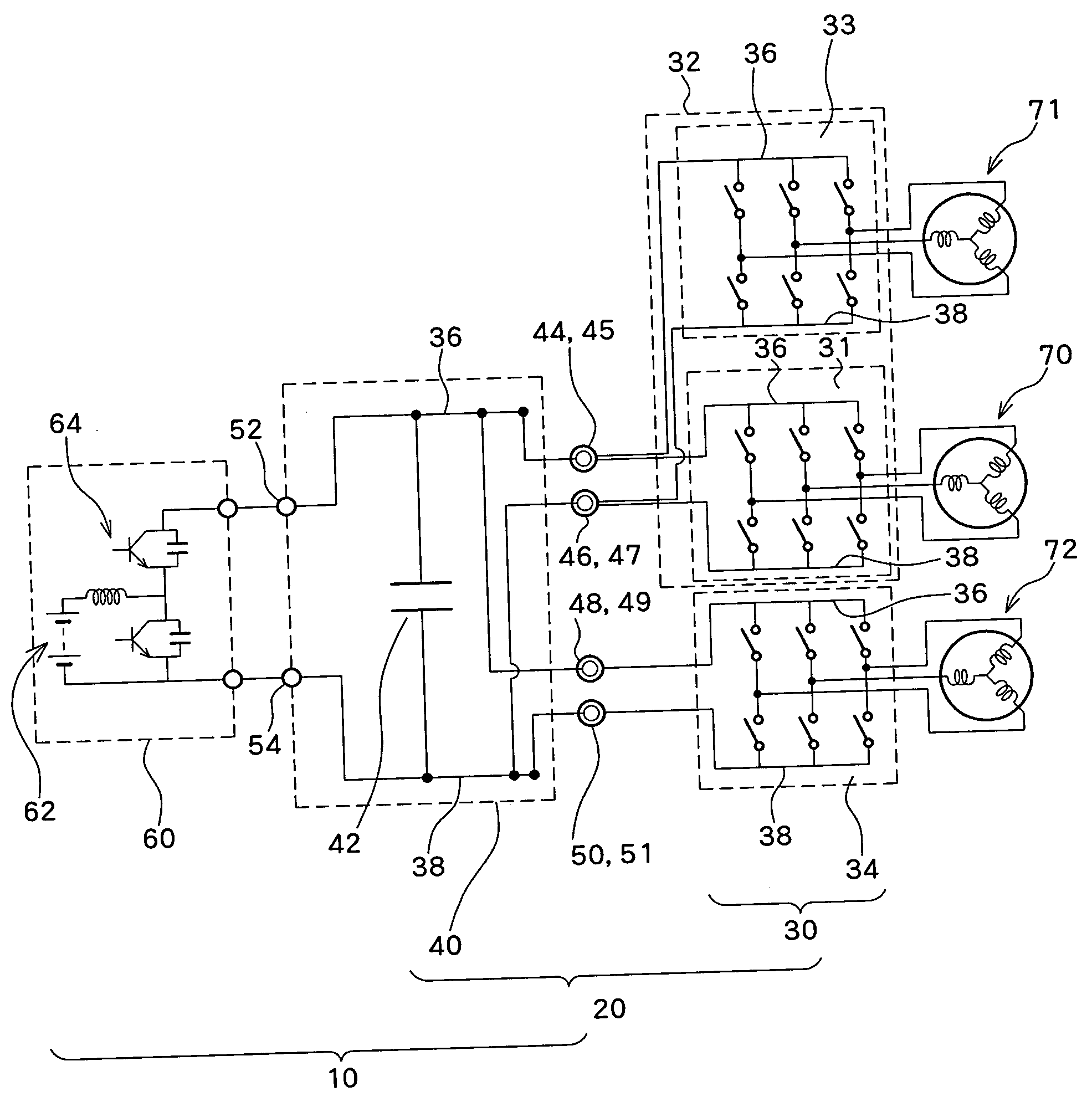
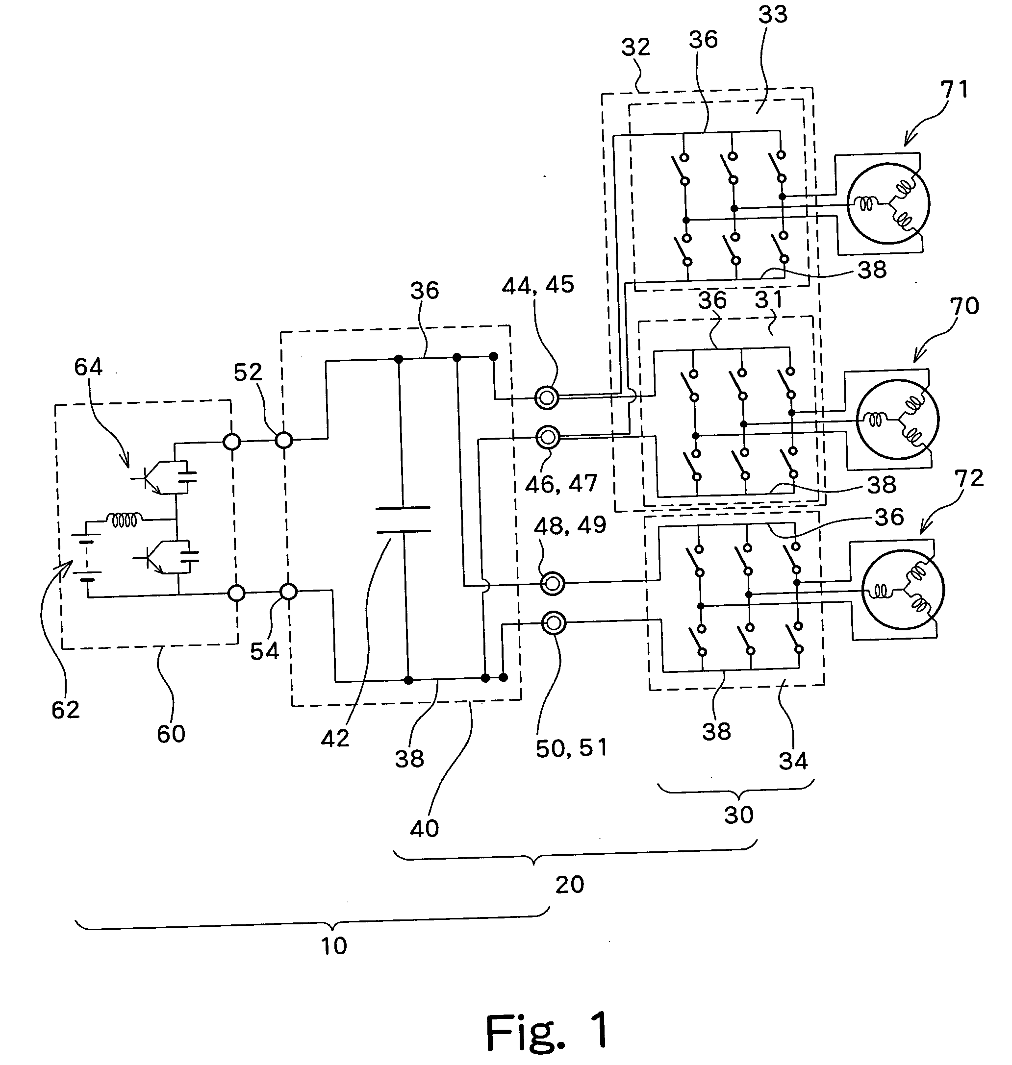
[0026] A preferred embodiment of the present invention will be described below with reference to the drawings. Although in the following explanation, it is assumed that an inverter unit for a vehicle is configured by two inverter circuit modules and one capacitor module, more than two inverter circuit modules may be provided. For example, in addition to a main inverter circuit module to be used for driving power to and electric power generation from the front-wheel drive vehicle and a sub inverter circuit module to be used for driving power to a rear-wheel drive vehicle, an inverter circuit module for air conditioner or the like, to which a voltage or the like is adapted, can be connected to the vehicle-mounted inverter unit. In addition, the installation locations for each external terminal are described below as an illustrated example, and other locations may be used as long as the inverter circuit module can be connected to the capacitor module.

[0027]FIG. 1 is a block diagram sh...


PUM


Abstract

An inverter unit for vehicle (20) is formed in such a manner that a capacitor module (40) is stacked on the upper portions of a main inverter circuit module (32) and a sub inverter circuit module (34) so as to connect the corresponding external terminals by a bolt (66). Here, by matching a positive electrode terminal (44) and a negative electrode terminal (46) of the capacitor module (40) with a positive side electrode terminal (45) and a negative side electrode terminal (47) of the main inverter circuit module (32), and at the same time by matching a positive electrode terminal (48) and a negative electrode terminal (50) of the capacitor module (40) with a positive side electrode terminal (49) and a negative side electrode terminal (51) of the sub inverter circuit module (34), responsible terminals are connected with this bolt (66) each other.

Description


Claims


Application Information

Patent Timeline
Owner TOYOTA JIDOSHA KK
Why Eureka
Try Eureka