Phase-locked loop with VCO tuning sensitivity compensation

a phase-locked loop and sensitivity compensation technology, applied in the field of phase-locked loops, can solve the problem that the linearity of the vco gain (ksub>vco/sub>) becomes a serious challenge, and achieve the effect of reducing the variation of the loop bandwidth of the pll

Active Publication Date: 2006-09-21
MEDIATEK INC
View PDF9 Cites 17 Cited by
  • Summary
  • Abstract
  • Description
  • Claims
  • Application Information

AI Technical Summary

Benefits of technology

[0007] The main objective of the present invention is to provide a phase-locked loop (PLL) capable of compensating the VCO tuning sensitivity so as to minimize the variation of the loop bandwidth of the PLL.
[0009] The loop filter is used for filtering the phase difference signal to output a frequency controlled signal. The gain controller has an input coupled to receive the second feedback signal relative to the phase difference signal. The second feedback relates to the phase difference signal, and the gain controller also generates the gain controlled signal in response to the second feedback signal. The VCO has an input coupled to receive the frequency controlled signal; the VCO also outputs the output signal in response to the frequency controlled signal. The phase detector gain is adjusted in accordance with the second feedback signal, so as to compensate the variation of the VCO gain and to make the loop bandwidth stable.

Problems solved by technology

However, when the PLL system is integrated into an integrated circuit (IC), the linearity of the VCO gain (KVCO) becomes a seriously challenging issue.
Therefore, it is still a problem how to compensate the loop bandwidth of a PLL having an analog phase detector in an IC.

Method used


Image

  • Phase-locked loop with VCO tuning sensitivity compensation
  • Phase-locked loop with VCO tuning sensitivity compensation
  • Phase-locked loop with VCO tuning sensitivity compensation

Examples


Embodiment Construction

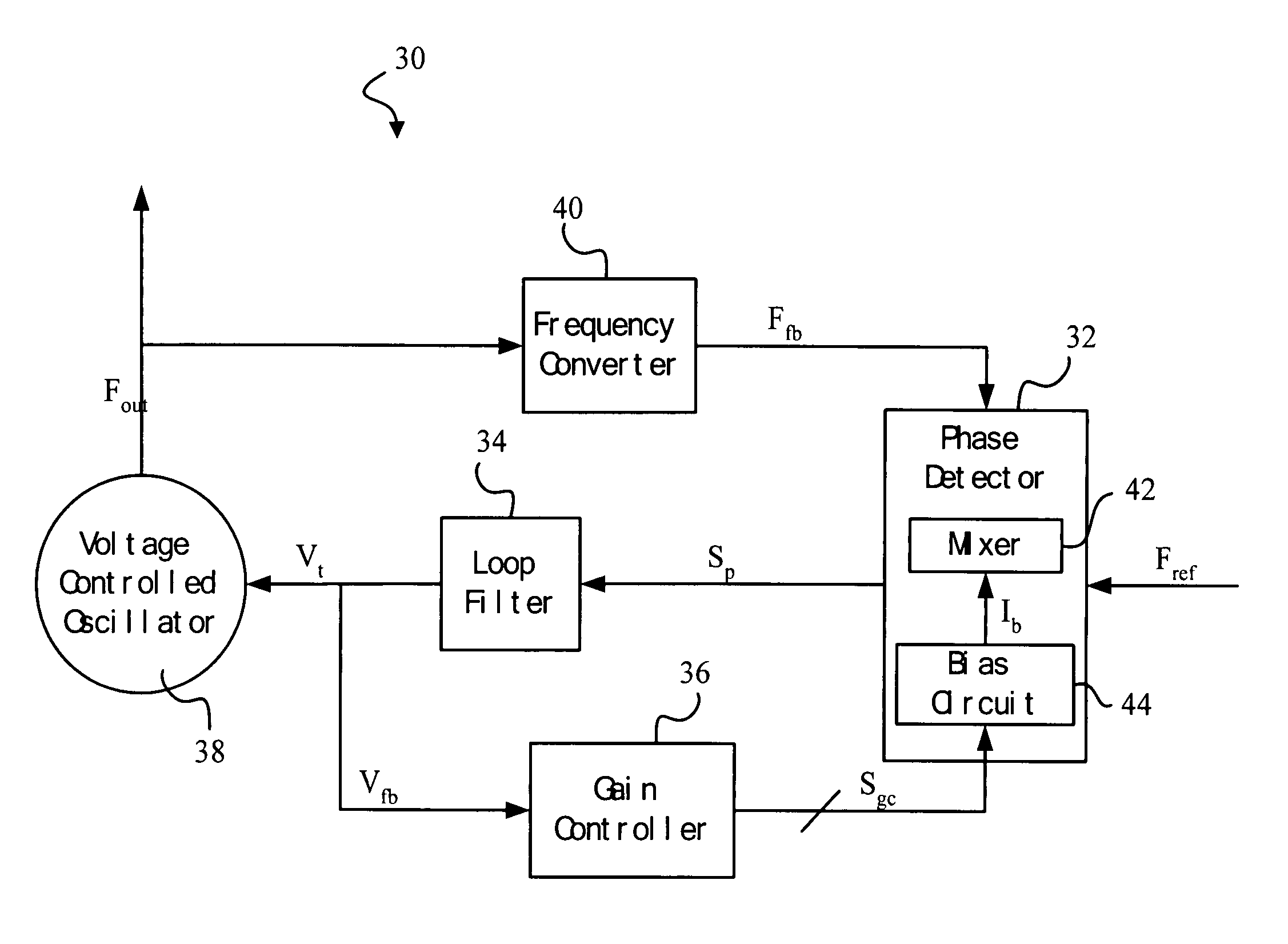
[0029] Referring to FIG. 6, FIG. 6 is a system block diagram of the phase-locked loop (PLL) 30 according to an embodiment of the present invention. The present invention provides a PLL 30; the PLL 30 comprises a phase detector 32, a loop filter 34, a gain controller 36, a voltage controlled oscillator (VCO) 38, and a frequency converter 40.

[0030] The phase detector 32 is an analog phase detector; it is used for receiving a first feedback signal (Ffb), a reference signal (Fref), and a gain controlled signal (Sgc) and for outputting a phase difference signal (Sp) in response to a phase difference (Δ) between the first feedback signal (Ffb) and the reference signal (Fref). A phase detector gain (KPD) of the phase detector 32 is defined as a ratio of the phase difference signal (Sp) to the phase difference (Δ). The phase detector gain (KPD) of the phase detector 32 is adjustable based on the gain controlled signal (Sgc).

[0031] As an example, the phase detector 32 comprises a mixer 42 ...


PUM


Abstract

The invention provides a phase-locked loop (PLL). Since a loop bandwidth of the PLL is a function of a gain of a phase detector and a gain of a voltage controlled oscillator (VCO), by adjusting the gain of the phase detector, the variation of the gain of the VCO (i.e., the tuning sensitivity) is compensated, so that the loop bandwidth of the PLL becomes more stable.

Description

BACKGROUND OF THE INVENTION [0001] This present invention relates to a phase-locked loop (PLL); more particularly, the present invention relates to a PLL capable of compensating the VCO tuning sensitivity by adjusting the phase detector gain according to the VCO tuning sensitivity so as to minimize the variation of the loop bandwidth of the PLL. [0002] In communication systems, the phase-locked loop (PLL) is a device used for generating an output signal having a specific phase and a specific frequency. In order to achieve this goal, it is desired that the variation of the loop bandwidth (W) of the PLL could be minimized as much as possible. [0003] Referring to FIG. 1, FIG. 1 is a system block diagram of a conventional PLL 10. The conventional PLL 10 comprises a phase detector 12, a loop filter 14, a voltage controlled oscillator (VCO) 16, and a frequency converter 18. The phase detector 12 is used for receiving an input signal (F1) and a reference signal (FR) and for comparing the p...

Claims


Application Information

Patent Timeline
Patent Type & Authority Applications(United States)
IPC IPC(8): H03L7/00H03L7/06
CPCH03L7/085H03L7/0898H03L7/093H03L2207/05H03L7/18H03L7/185H03L7/1072
Inventor KUO, CHANG-FUTSENG, PO-SENWANG, SHOU-TSUNGKO, LING-WEI
Owner MEDIATEK INC
Why Eureka
Try Eureka