
Multi-mode wireless polar transmitter architecture

Active Publication Date: 2006-09-21
AVAGO TECH INT SALES PTE LTD
View PDF4 Cites 53 Cited by
  • Summary
  • Abstract
  • Description
  • Claims
  • Application Information

AI Technical Summary

Benefits of technology

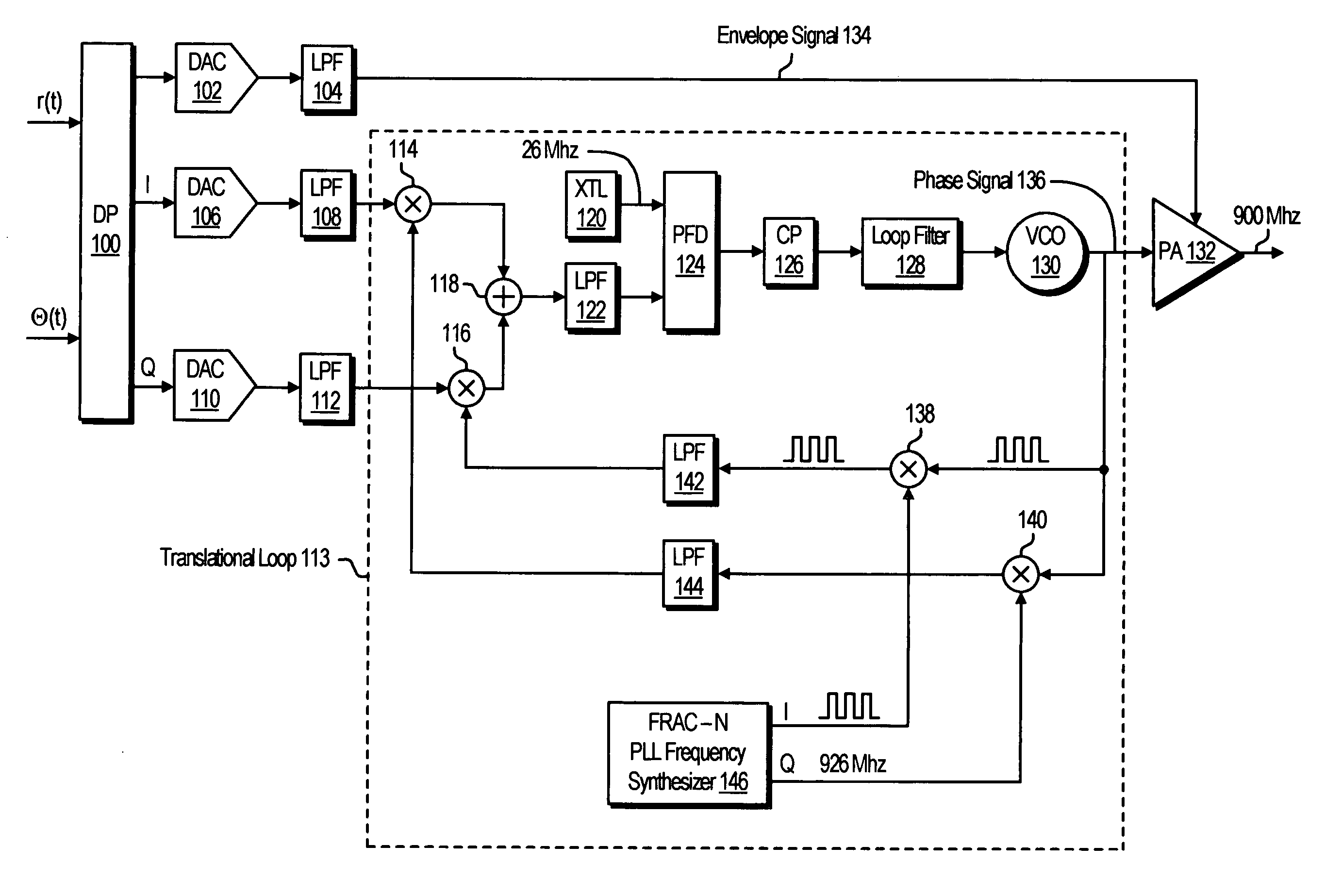
[0019] The first filter switching controller receives the second control signal and produces a first filter control signal to select one of a first equalizer filter value and a second equalizer filter value based on the signal bandwidth of the outgoing digital signal. The equalizer filters are programmable with one of the first filter value and the second filter value based on the first filter control signal to filter the envelope signal and the p

Problems solved by technology

In any mobile communication system, the radio spectrum is a very limited resource shared by all users.
In practice, the power spectrum emitted from an EDGE transmitter will not be ideal due to

Method used


Image

  • Multi-mode wireless polar transmitter architecture
  • Multi-mode wireless polar transmitter architecture
  • Multi-mode wireless polar transmitter architecture

Examples


Example

DETAILED DESCRIPTION OF THE DRAWINGS

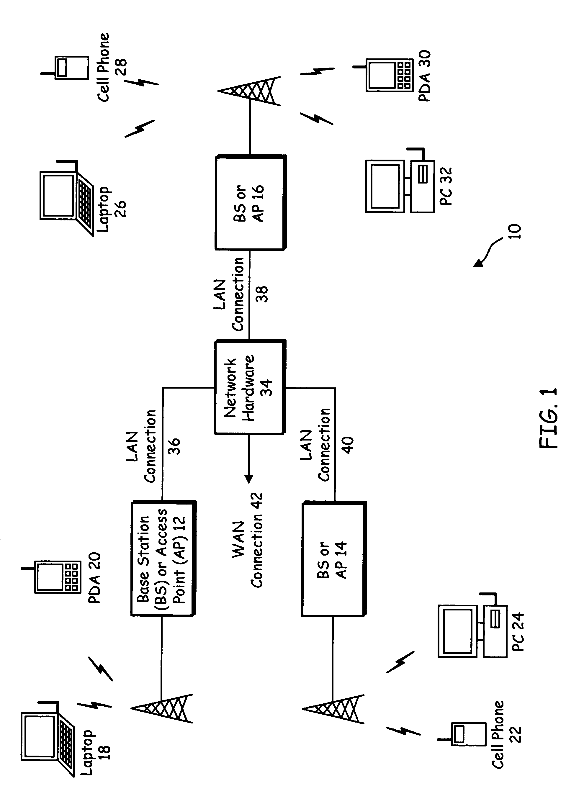
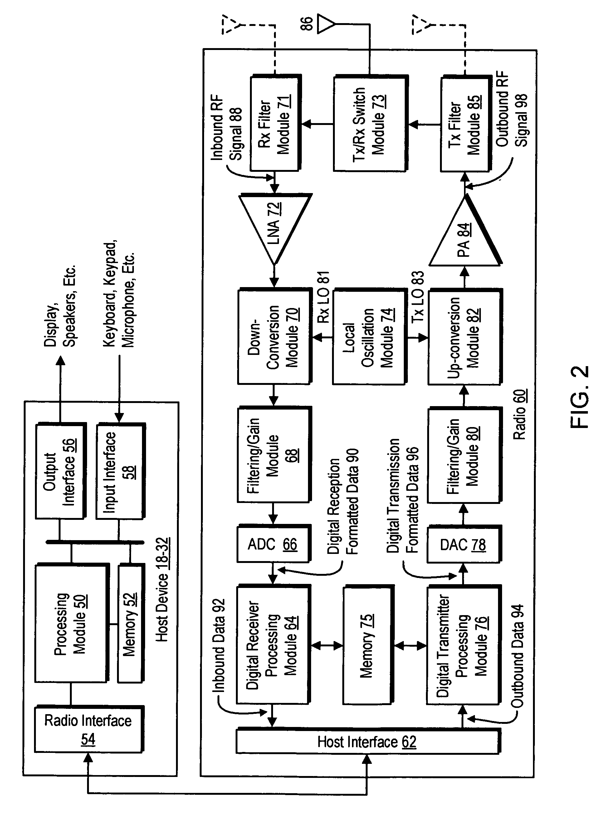
[0034]FIG. 1 is a functional block diagram illustrating a communication system 10 that includes a plurality of base stations or access points (APs) 12-16, a plurality of wireless communication devices 18-32 and a network hardware component 34. The wireless communication devices 18-32 may be laptop computers 18 and 26, personal digital assistants 20 and 30, personal computers 24 and 32 and / or cellular telephones 22 and 28. The details of the wireless communication devices will be described in greater detail with reference to FIGS. 2-9.

[0035] The base stations or APs 12-16 are operably coupled to the network hardware component 34 via local area network (LAN) connections 36, 38 and 40. The network hardware component 34, which may be a router, switch, bridge, modem, system controller, etc., provides a wide area network connection 42 for the communication system 10. Each of the base stations or access points 12-16 has an associated antenna or antenna...


PUM


Abstract

A radio transmitter within a transceiver includes a digital processor and analog circuitry for modulating and transmitting an outgoing digital signal in multiple modes of operation. The digital processor digitally modulates the outgoing digital signal to produce one of a constant envelope modulated digital signal and a variable envelope modulated digital signal based on the particular modulation scheme being used to modulate the outgoing digital signal. In addition, the digital processor filters the outgoing digital signal using filter values selected based on the signal bandwidth of the outgoing digital signal. The analog circuitry converts digital envelope and phase signals of the modulated digital signal to analog envelope and phase signals, and up-converts the analog phase signal from an IF signal to an RF signal, using a loop filter that is programmable based on the signal bandwidth of the outgoing digital signal.

Description

BACKGROUND [0001] 1. Technical Field [0002] The present invention relates to wireless communications and, more particularly, wideband wireless communication systems. [0003] 2. Related Art [0004] Modern wireless RF transmitters for applications, such as cellular, personal, and satellite communications, employ digital modulation schemes such as frequency shift keying (FSK) and phase shift keying (PSK), and variants thereof, often in combination with code division multiple access (CDMA) communication. Independent of the particular communications scheme employed, the RF transmitter output signal, sRF(t), can be represented mathematically as sRF(t)=r(t)cos(2πfct+θ(t))  (1) where fc denotes the RF carrier frequency, and the signal components r(t) and θ(t) are referred to as the envelope and phase of sRF(t), respectively. [0005] Some of the above mentioned communication schemes have constant envelope, i,e., r(t)=R, and these are thus referred to as constant-envelope communications scheme...

Claims


Application Information

Patent Timeline
IPC IPC(8): H04L27/12
CPCH04L25/03834H04L27/0008H04L27/361H04L27/367
Inventor JENSEN, HENRIK T.
Owner AVAGO TECH INT SALES PTE LTD
Learn More