Card reader and writer

a card reader and card reader technology, applied in the field of card readers and writers, can solve the problems of inability to perform a stable operation, unstable card loading state, etc., to prevent card jam and skimming, perform read and write of card information positively, and improve accuracy and positive

Inactive Publication Date: 2006-09-21
HITACHI OMRON TERMINAL SOLUTIONS CORP
View PDF19 Cites 12 Cited by
  • Summary
  • Abstract
  • Description
  • Claims
  • Application Information

AI Technical Summary

Benefits of technology

[0025] According to the construction of the present invention, since the card inserting direction and the head moving direction are set perpendicular to each other and the read and write of information for the card are performed by moving the head, the card holding state can be made stabler than in the conventional manual type card reader and writer. Consequently, the read and write of information from and to the card can be done more accurately and positively in comparison with the conventional device.
[0026] In particular, according to the present invention, since a card can be held positively even by the structure wherein the card is not completely inserted into the case, it is possible to constitute an extremely space-saved card reader and writer wherein part of the card inserted is exposed to the exterior. Consequently, it is possible to prevent phishing, card jam and skimming and perform read and write of card information positively.

Problems solved by technology

However, even in a card reader and writer wherein a head moves in a card information read / write direction perpendicular to a card insertion / ejection direction as mentioned above, there is the possibility of occurrence of card jam and phishing as in the automatic type if the device is of a structure wherein the card is inserted completely into the interior of the device.
However, if the card is not completely inserted into the interior of the device, the state of loading of the card becomes unstable and it has heretofore been impossible to perform a stable operation at the time of moving the head to read or write information.

Method used


Image

  • Card reader and writer
  • Card reader and writer
  • Card reader and writer

Examples


Embodiment Construction

[0032] A card reader and writer embodying the present invention will be described hereinunder with reference to FIGS. 1 to 4.

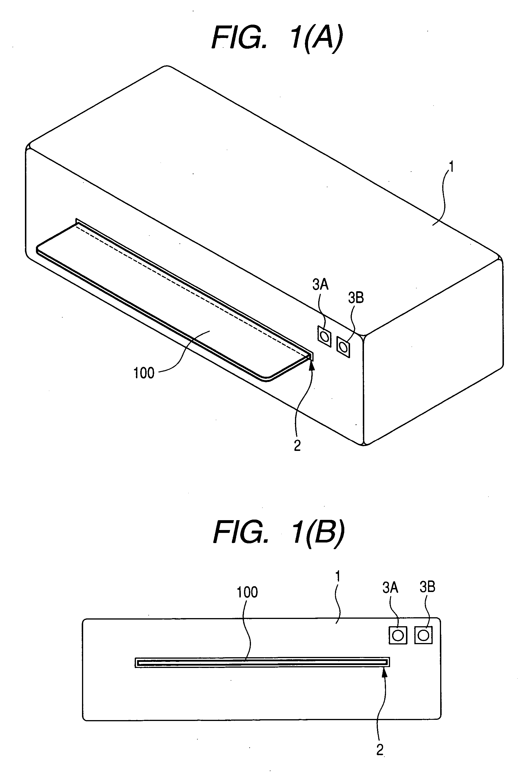
[0033]FIG. 1A is an appearance perspective view of the card reader and writer of this embodiment and FIG. 1B is a front view thereof.

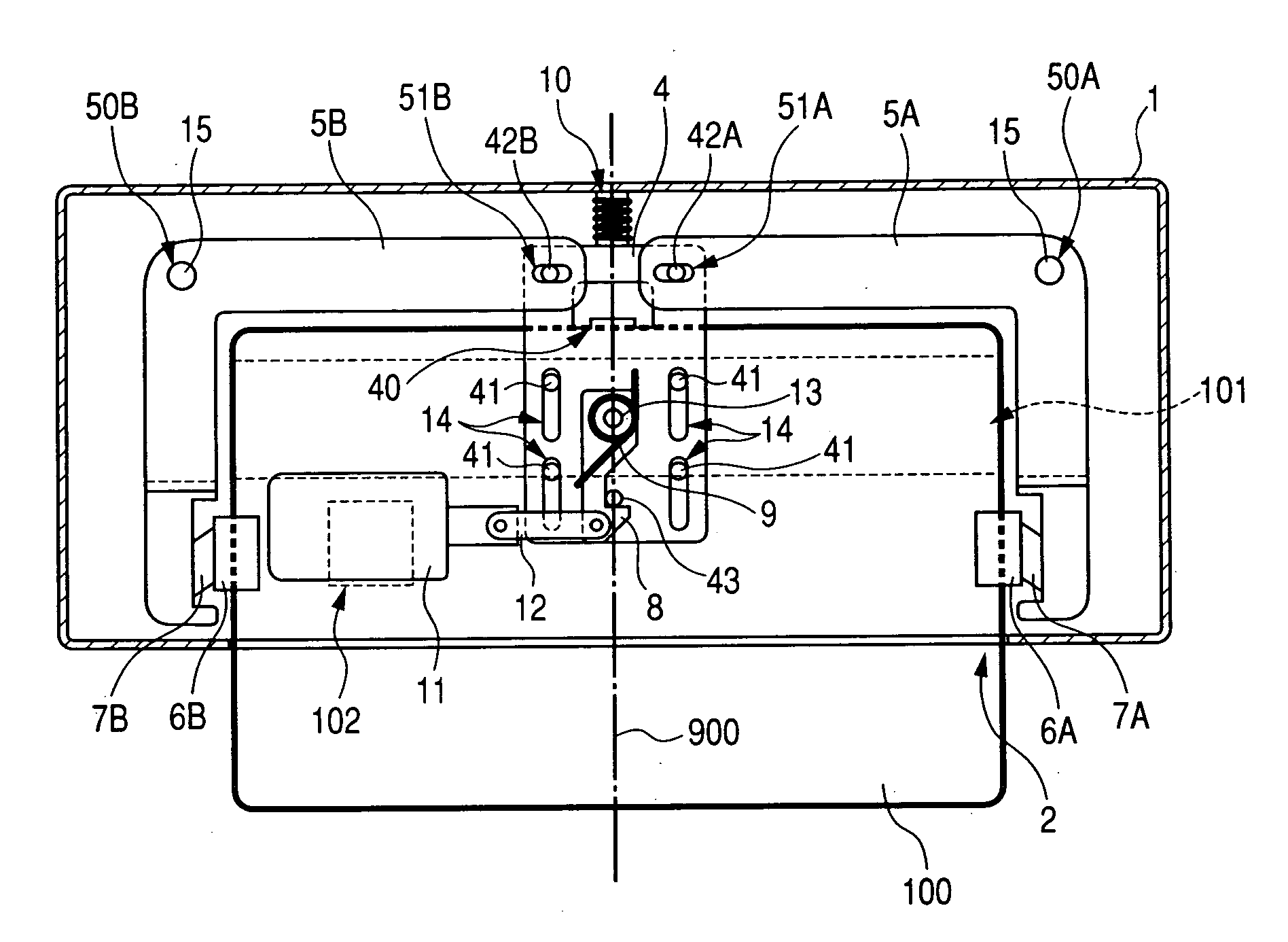
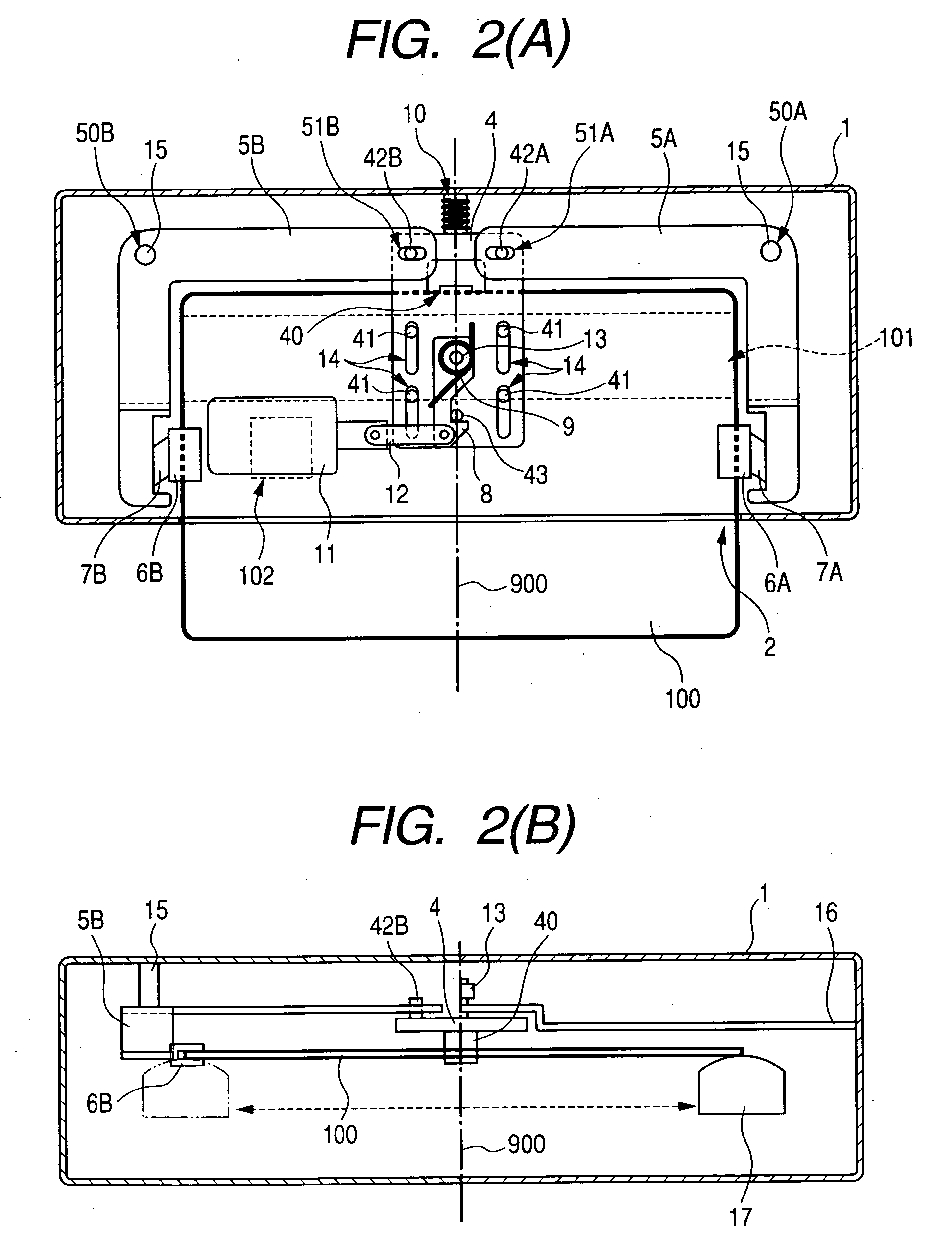
[0034]FIG. 2A is a sectional plan view of a card 100 held in the card reader and writer shown in FIG. 1, and FIG. 2B is a sectional front view thereof.

[0035] The card reader and writer has a card inlet 2 and lamps 3A and 3B in the front of a case 1, the case 1 having a predetermined shape such as, for example, a generally rectangular parallelepiped shown in FIG. 1. The case 1 is formed to be long in its width direction and short in its depth direction as viewed from the front, according to the shape of the card 100 to be inserted. The card 100 is inserted in such a manner that an extending direction of a magnetic information recording portion 101 is parallel to the width direction (the direction connecting both the lateral sid...


PUM


Abstract

A card reader and writer is provided which can perform read and write operation on a card in a stable manner although it is configured such that a card inserting direction is perpendicular to a head moving direction and the card is partially inserted into the device.
When a card 100 is inserted into a case 1 and comes into abutment against a depth abutment member 40 of a slider 4, the slider 4 moves in the depth direction. With this movement, pivotal levers 5A and 5B pivot and holders 6A and 6B come into abutment against end faces of the card 100 in the width direction to grip the card in the width direction. At the same time, in accordance with the movement of the slider 4, an engaging shaft 43 of the slider causes a pivotal engaging member 8 to pivot and comes into engagement with an engaging recess 82 after a predetermined amount of the pivotal movement.

Description

CLAIM OF PRIORITY [0001] The present application claims priority from Japanese application JP2005-76940 filed on Mar. 17, 2005, the content of which is hereby incorporated by reference into this application.BACKGROUND OF THE INVENTION [0002] The present invention relates to a card reader and writer for reading and writing information from and to a magnetic information recording card. In particular, the present invention relates to a card reader and writer for reading and writing information by moving a head in a card width direction perpendicular to a card insertion direction. [0003] The conventional card reader and writers has two types: an automatic type wherein a card is inserted and ejected automatically; a manual type wherein a card is not automatically inserted and ejected. In many conventional card reader and writers, the card insertion / ejection direction and the head moving direction are the same. [0004] An automatic type card reader and writer performs read processing and w...

Claims


Application Information

Patent Timeline
Patent Type & Authority Applications(United States)
IPC IPC(8): H01R13/62
CPCG06K13/08
Inventor ISHII, MASAYUKI
Owner HITACHI OMRON TERMINAL SOLUTIONS CORP
Why Eureka
Try Eureka