Vent pipe cover

a vent pipe and cover technology, applied in the field of covers or shields, can solve the problems of preventing small animals or other creatures from entering the vent pipe, problems in the plumbing system, and reducing so as to facilitate the movement of precipitation, reduce the encroachment of leaves, and reduce the risk of ice clogging

Inactive Publication Date: 2006-09-21
GRASSMAN MICHAEL D
View PDF13 Cites 125 Cited by
  • Summary
  • Abstract
  • Description
  • Claims
  • Application Information

AI Technical Summary

Benefits of technology

[0015] It is a further object of an exemplary embodiment to provide a vent pipe cover that may be at least partially insulated to retard heat loss through the plumbing system.
[0016] It is a further object of an exemplary embodiment to provide a vent pipe cover that reduces intrusion of the elements, but does not hinder the functioning of the plumbing drain system.
[0017] It is a further object of an exemplary embodiment to provide a vent pipe cover that lessens the encroachment of sticks, leaves, and animals into the plumbing drain system.
[0018] It is a further object of an exemplary embodiment to enhance the appearance of a protruding vent pipe.
[0023] In general, the first apertures are disposed in an upper portion of the inner wall and the second apertures may be disposed in an upper portion of the outer wall. In some embodiments, each of the first apertures are offset from the second apertures, so that none of the apertures are radially aligned. One or more of the apertures may include vane members to reduce encroachment of leaves, sticks, animals, insects, and the like into the vent pipe.
[0024] The apparatus may include an insulator disposed in the space between the outer wall and the inner wall to reduce heat loss through the vent pipe.

Problems solved by technology

However, the open-ended structures do not prevent small animals or other creatures from entering the vent pipe.
In colder climates, problems in plumbing systems have been traced to ice clogging the vent pipe.
Thus, there exists a need in the art for a vent pipe cover which decreases the risk of ice clogs.
Also in colder climates, the vent pipe may allow unnecessary heat loss from the building structure.

Method used


Image

  • Vent pipe cover
  • Vent pipe cover
  • Vent pipe cover

Examples


Embodiment Construction

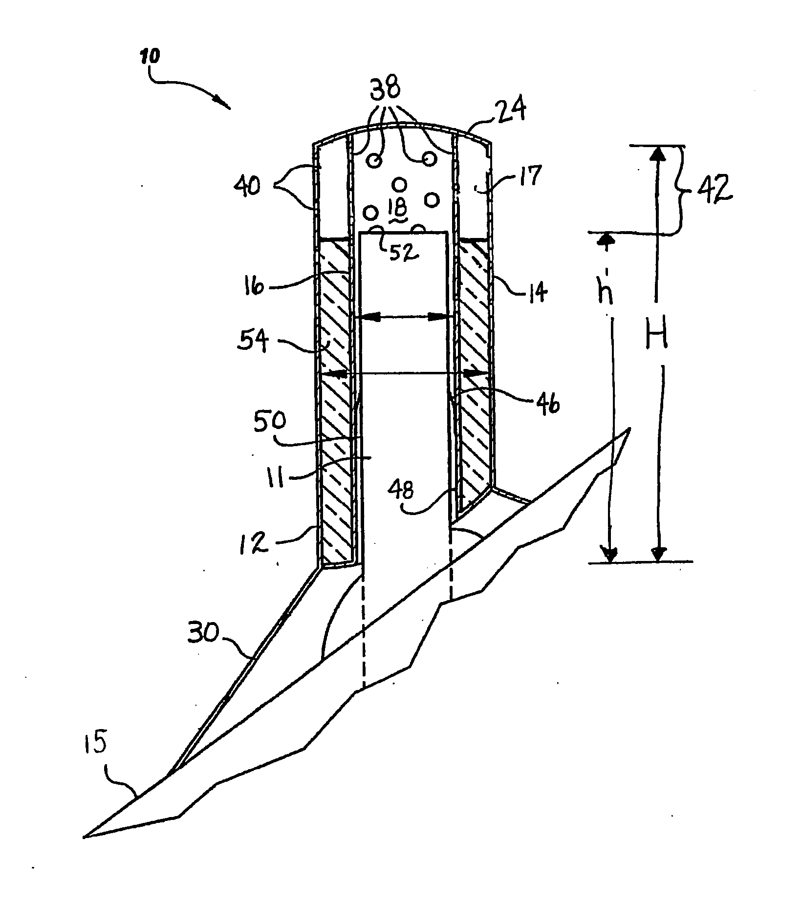
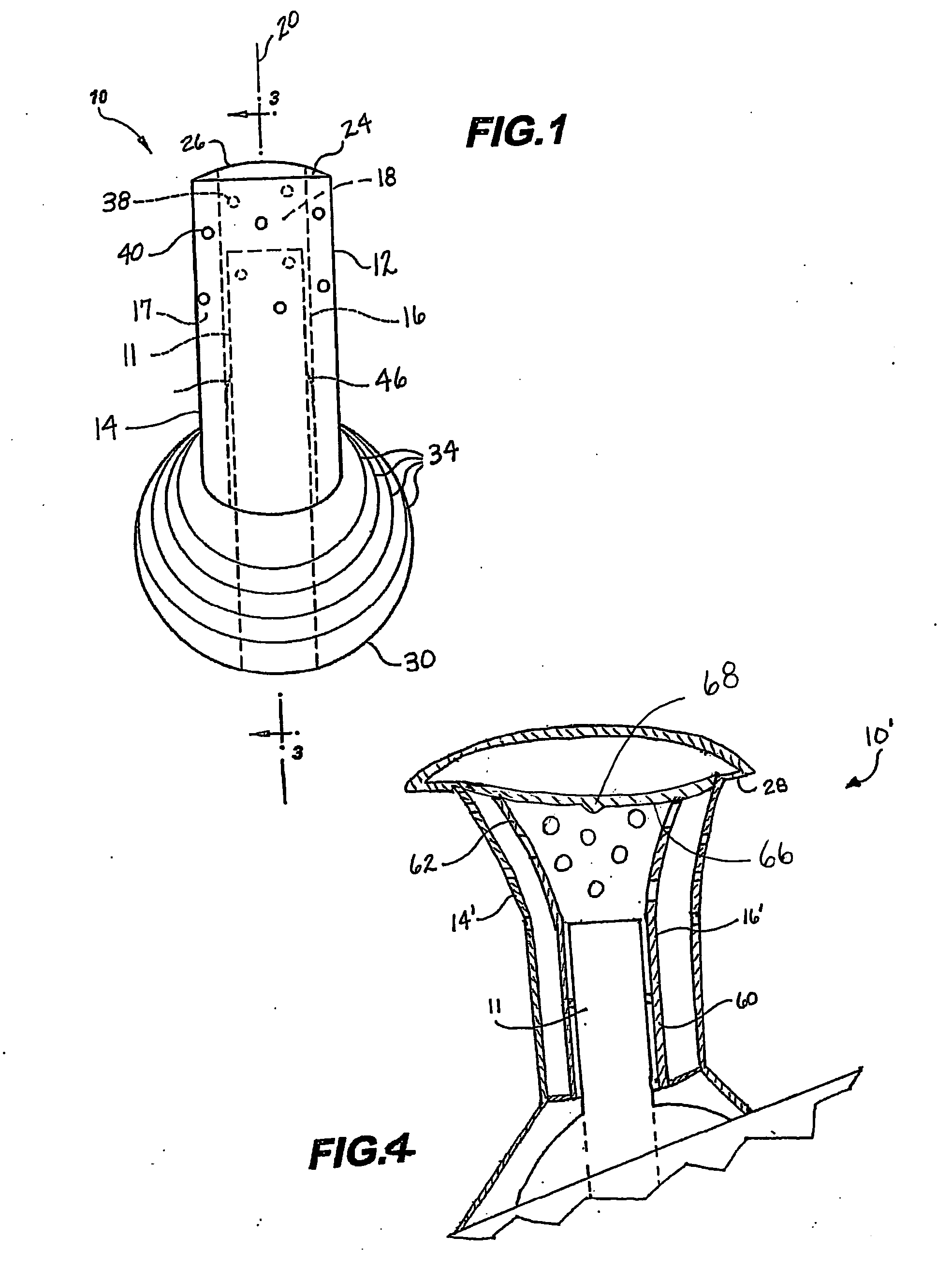
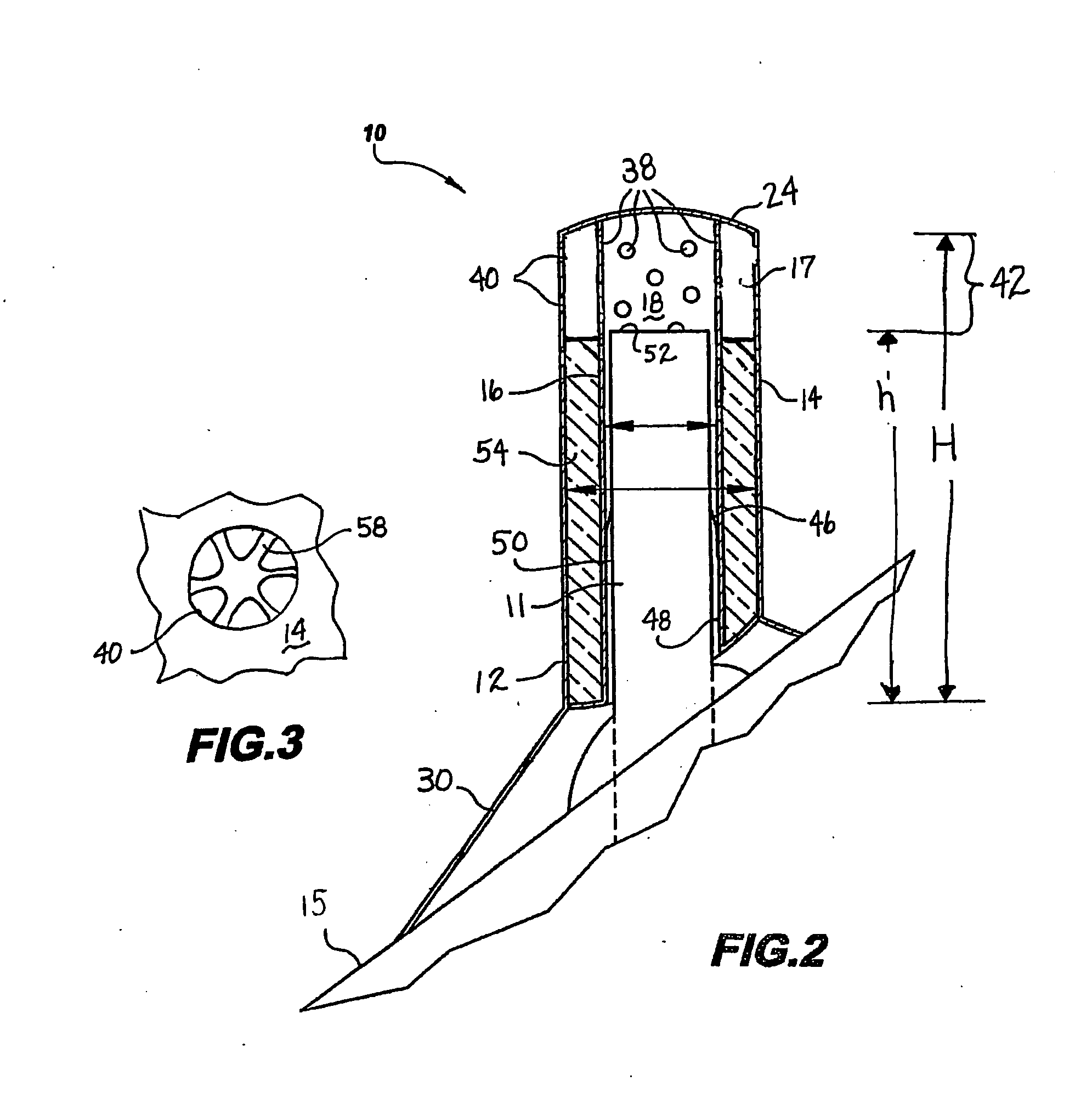
[0037] Referring now to the drawings and particularly to FIGS. 1-2, there is shown therein an exemplary embodiment of an apparatus according to the invention and generally designated by the reference numeral 10. Apparatus 10 is generally referred to herein as a vent pipe cover adapted to fit over an exposed vent pipe 11 protruding through the roof 15 of a structure.

[0038] In an exemplary embodiment, apparatus 10 comprises a generally double walled cylindrical body 12 having an outer wall 14 and an inner wall 16, defining an generally cylindrical space 17 therebetween. In the Figures, the outer wall 14 and inner wall 16 are illustrated as having generally equal thicknesses. The embodiment shown is merely illustrative and other constructions are contemplated within the scope of the invention.

[0039] Inner wall 16 defines a central cavity 18 extending along a longitudinal axis 20. Body 12 is closed at its upper end by a cap 24 which also closes the upper end of the central cavity 18. ...


PUM


Abstract

A vent pipe cover having a double walled body for engaging the outermost surface of a vent pipe. The upper end of the body is capped and gas flow passages are provided by first apertures extending through an inner wall and second apertures extending through an outer wall. The apertures are generally formed in at least an upper portion of the body. The body comprises a length sufficient to provide adequate head space for the flow of gasses above the upper edge of the pipe. An insulator may be positioned between the inner and outer walls to reduce heat loss through the pipe. A flared skirt extending from the lower surface of the outer wall includes cutting lines to adapt the vent pipe cover to roofs of differing pitches. One or more deformable clips are used to releaseably engage an inner most surface of the pipe cover with the outermost surface of the vent pipe.

Description

CROSS REFERENCE TO RELATED APPLICATION [0001] This Application claims benefit pursuant to 35 U.S.C. §19(e) of Provisional Application 60 / 594,152 filed Mar. 15, 2005, the disclosure of which is incorporated herein by reference.TECHNICAL FIELD [0002] This invention relates to covers or shields for roof vent pipes. More particularly, the invention relates to a multi-walled vent cover having a capped end and vent openings extending through outer and inner walls. BACKGROUND ART [0003] U.S. Pat. No. 5,245,804 is directed to a roof vent pipe shield including an outer plastic cylinder and an inner plastic cylinder connected at one end by fusion bonded portions such that there is a space between the cylinders. A through passage extends through upper and lower open ends of the inner cylinder. A flared portion extends from the lower end of the outer cylinder for engagement with the roof. Cutting guide lines are provided on the inner surface of the flared portion to enable roofs of different pi...

Claims


Application Information

Patent Timeline
Patent Type & Authority Applications(United States)
IPC IPC(8): F23J13/08
CPCF23J13/08F23J2213/50F23J2900/13005
Inventor GRASSMAN, MICHAEL D.
Owner GRASSMAN MICHAEL D
Why Eureka
Try Eureka