Cardiac contractility modulation device having anti-arrhythmic capabilities and method of operating thereof

a contractility modulation and cardiac technology, applied in the field of antiarrhythmic cardiotherapy devices, can solve the problems of cardiac tachy-arrhythmias being delivered to the heart without defibrillating shock therapy, and the heart being affected by cardiac tachy-arrhythmia detection and/or classification, etc., and achieve the effect of modulating the contractility

Inactive Publication Date: 2006-09-21
IMPULSE DYNAMICS NV
View PDF99 Cites 113 Cited by
  • Summary
  • Abstract
  • Description
  • Claims
  • Application Information

AI Technical Summary

Benefits of technology

[0023] There is therefore provided, in accordance with a preferred embodiment of the present invention, a cardiac contractility modulating device. The device includes an anti-arrhythmic therapy unit for detecting a cardiac arrhythmia in a heart of a patient based on processing electrical signals related to cardiac activity of the heart, and for delivering anti-arrhythmic therapy to the heart in response to detecting of the cardiac arrhythmia. The device further includes a cardiac contractility modulating unit configured for delivering cardiac contractility modulating signals to the heart for modulating the contractility of at least a portion of the heart. The cardiac contractility modulating unit is operatively connected to the anti-arrhythmic unit for providing the anti-arrhythmic therapy unit with first control signals associated with the delivery of the cardiac contractility modulating signals to the heart, to prevent interference of the cardiac contractility modulating signals with the detecting of the cardiac arrhythmia by the anti-arrhythmic device. The device also includes at least one power source for energizing the anti-arrhythmic therapy unit and the cardiac contractility modulating unit.

Problems solved by technology

While such non-excitatory electrical signals do not lead to propagating myocardial action potentials, they may modulate the myocardial contractility in naturally or artificially paced cardiac beats.
The timing of the ETC signals must be carefully controlled since application of the ETC signal to the myocardium at an inappropriate time may be arrhythmogenic.
Unfortunately, the delivery of ETC signals to the myocardium may lead to electrical artifact signals sensed by the sense electrodes of the anti-arrhythmic device.
Such spurious detection of electrical artifacts induced by ETC signals may adversely affect the detection and / or classification of cardiac tachy-arrhythmias.
For example, such spurious event detection may result in classification of a normal heart rate as VT or VF leading to unnecessary and potentially dangerous defibrillating shock therapy being delivered to the heart.
Besides the increased patient risk and patient discomfort caused by such unnecessary delivery of defibrillation shock therapy, such erroneous detection of VF followed by defibrillating shock therapy may lead to unnecessary drain on the battery of the device, thus shortening the useful life in implanted devices.
Additionally, in devices capable of delivering cardioversion therapy, spurious event detection caused by ETC induced electrical artifacts may result in unnecessary delivery of cardioversion therapy by the device which has the disadvantage of unnecessary battery drain and which may increase patient risk.
Another problem which may result from delivering of ETC signals to the heart of a patient which is monitored by an anti-arrhythmic device such as, inter alia, a defibrillator / cardioverter device, is the possible interference of ETC induced electrical artifacts with the operation of detection circuitry utilizing automatic gain control (AGC) or automatic threshold control (ATC).
ETC signal induced artifacts sensed by the defibrillator amplification circuits may cause an undesirable decrease in the gain of the amplifier circuits in defibrillators using AGC based algorithms which may lead to failure to detect VF signal.
ETC signal induced artifacts sensed by the defibrillator amplification circuits may also cause an undesirable increase in the threshold level in defibrillators using ATC based algorithms which may also lead to failure to detect VF signal.
The above described interference problems may be encountered in the operation of a variety of different prior art internal cardiac defibrillator (ICD) devices and automatic internal cardioverter defibrillator (AICD) devices, including tiered therapy devices capable of delivering different types of cardiac therapy such as anti-brady-arrhythmic pacing therapy, anti-arrhythmic cardioversion therapy, anti-arrhythmic defibrillating shock therapy, variable energy shock therapy, anti-tachycardia pacing therapy (ATP) and any combination thereof in the presence of ETC signals delivered by operating CCM or ETC devices.

Method used


Image

  • Cardiac contractility modulation device having anti-arrhythmic capabilities and method of operating thereof
  • Cardiac contractility modulation device having anti-arrhythmic capabilities and method of operating thereof
  • Cardiac contractility modulation device having anti-arrhythmic capabilities and method of operating thereof

Examples


Embodiment Construction

[0075] The following terms are used throughout the application:

TermDefinitionACAlternating CurrentAGCAutomatic Gain ControlAICDAutomatic Internal Cardioverter DefibrillatorATCAutomatic Threshold ControlATPAnti-Tachycardia PacingCCMCardiac Contractility ModulationCHFCongestive Heart FailureDCDirect CurrentECDExternal Cardiac DefibrillatorETCExcitable Tissue ControlICDInternal Cardiac DefibrillatorLUTLook Up TableSVTSupra Ventricular TachycardiaVFVentricular FibrillationVTVentricular Tachycardia

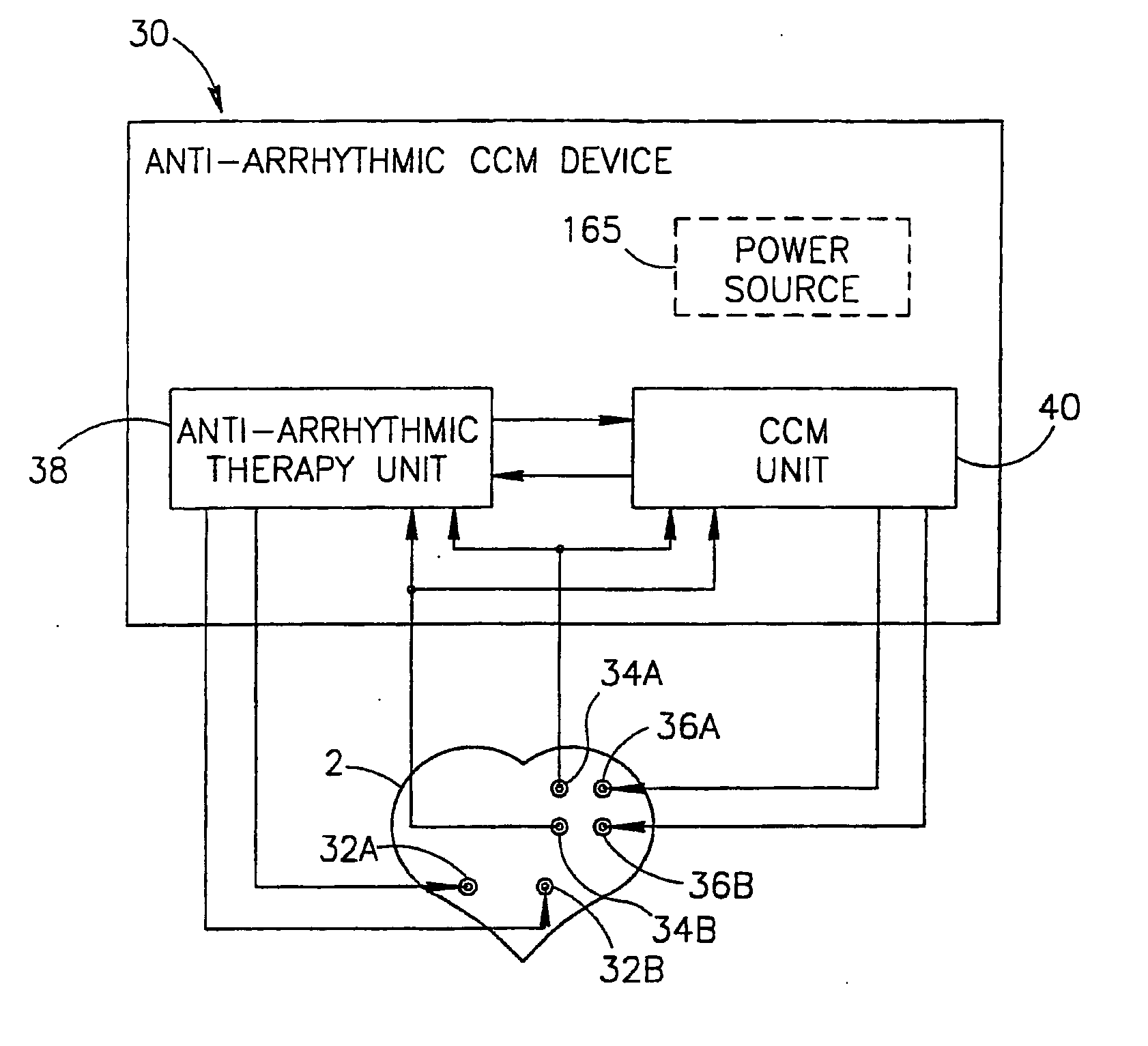
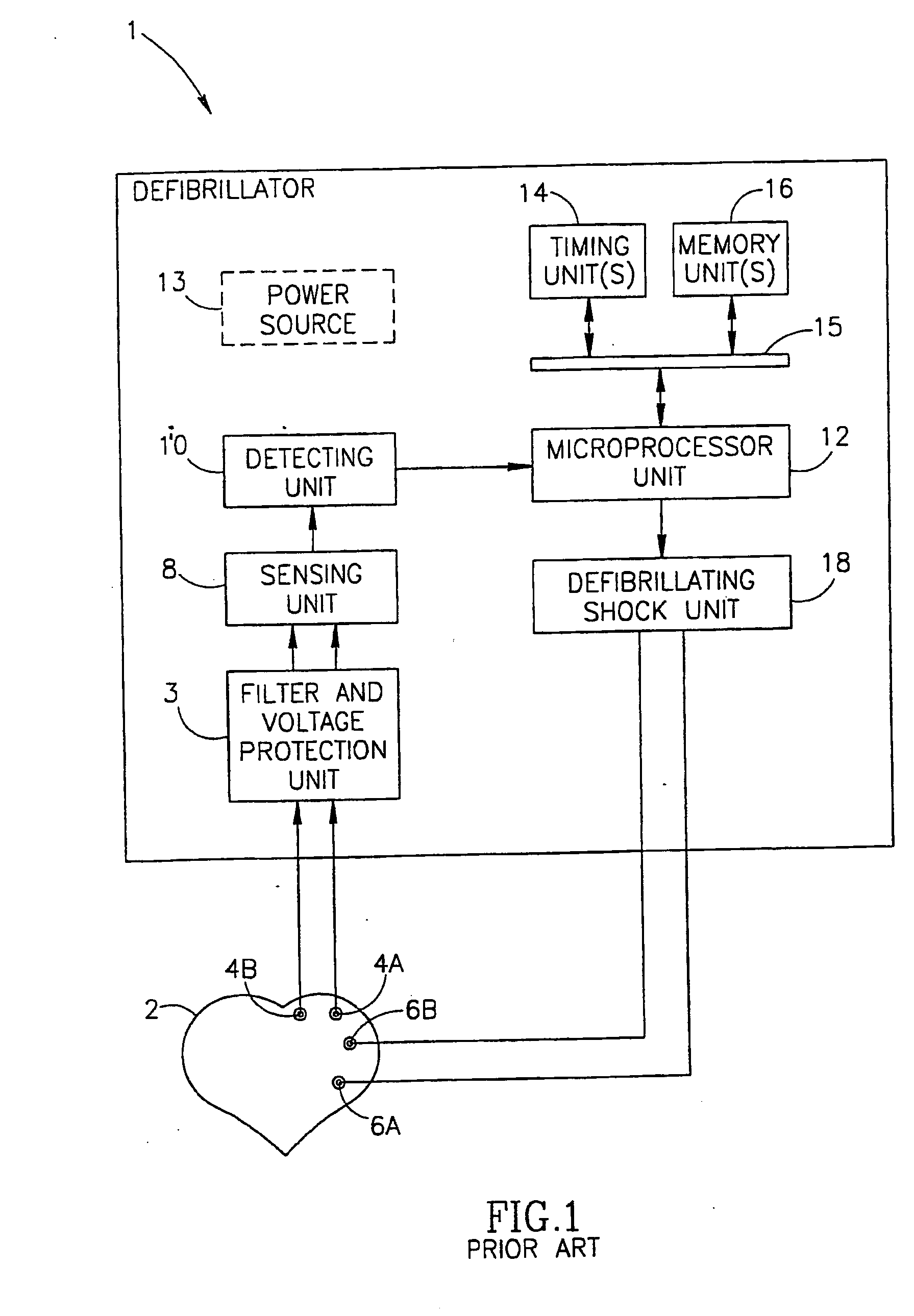
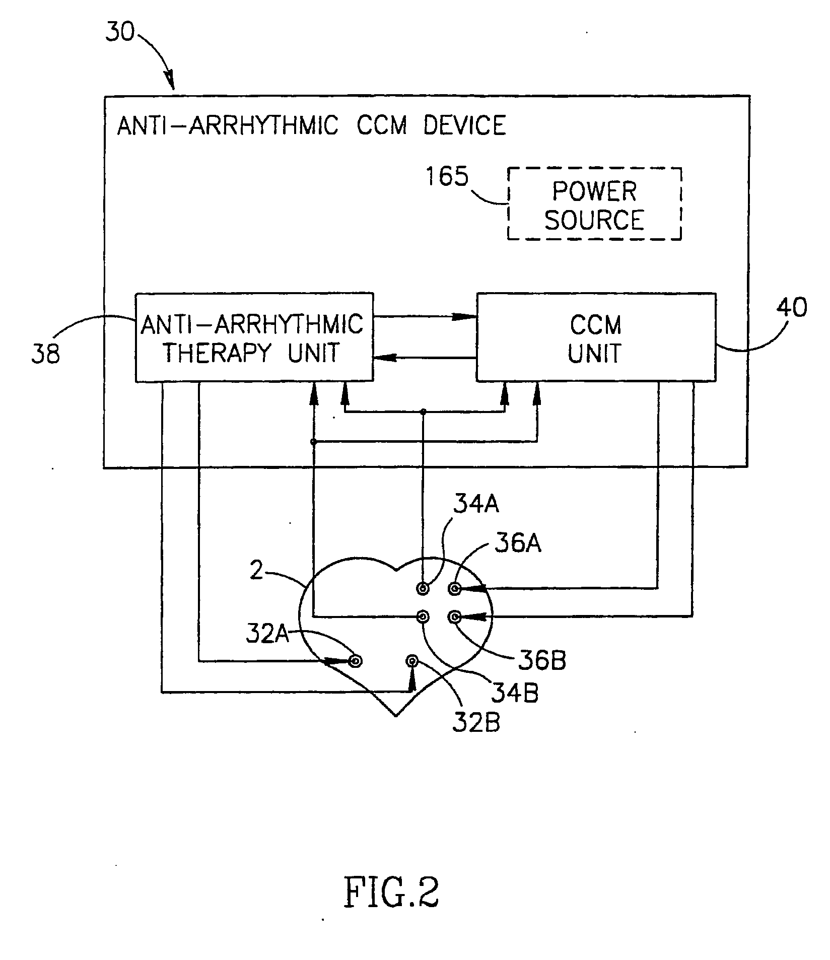
[0076] Reference is now made to FIG. 1 which is a schematic functional block diagram illustrating a prior art defibrillator device.

[0077] The defibrillator device 1 includes a filter and voltage protection unit 3 which is suitably electrically connected to sensing electrodes 4A and 4B which are implanted in or about the heart 2. The filter and high voltage protection unit 3 may includes various types of filtering circuitry for filtering the electrical signals sensed by the sensing electrodes...


PUM


Abstract

A cardiac contractility modulating (CCM) device (30) includes an anti-arrhythmic therapy unit (38) for detecting a cardiac arrhythmia in a heart (2) of a patient based on processing electrical signals related to cardiac activity sensed at the heart, and for delivering anti-arrhythmic therapy to the heart. The device includes a cardiac contractility modulating (CCM) unit (40) capable of delivering cardiac contractility modulating (CCM) signals to the heart for modulating the contractility of a portion of the heart. The device may provide to the anti-arrhythmic therapy unit control signals associated with the delivery of the CCM signals to the heart. The control signals may be used to prevent interference of the CCM signals with the detecting of the cardiac arrhythmia. The device (30) includes a power source. The device may be an implantable device or a non-implantable device. The device may also include a pacing unit.

Description

CROSS REFERENCES TO RELATED APPLICATIONS [0001] This Patent Application is related to and claims priority from commonly owned U.S. Provisional Patent applications Ser. No. 60 / 161,328, filed Oct. 25, 1999 entitled “CARDIAC CONTRACTILITY MODULATION DEVICE HAVING ANTI-ARRHYTHMIC CAPABILITIES AND A METHOD OF OPERATING THEREOF”, Ser. No. 60 / 161,899 filed Oct. 27, 1999 entitled “DEVICE FOR CARDIAC THERAPY”, and Ser. No. 60 / 161,900 filed Oct. 27, 1999 entitled “ANTI-ARRHYTHMIC DEVICE AND A METHOD OF DELIVERING ANTI-ARRHYTHMIC CARDIAC THERAPY”, all three Provisional Patent Applications are incorporated herein by reference in their entirety. Also, this patent application is a continuation of commonly owned, co-pending U.S. patent application Ser. No. 10 / 111,515, filed Oct. 30, 2002, also incorporated herein by reference in its entirety.FIELD OF THE INVENTION [0002] The present invention relates generally to the field of anti-arrhythmic cardiotherapy devices and more particularly to cardiac c...

Claims


Application Information

Patent Timeline
Patent Type & Authority Applications(United States)
IPC IPC(8): A61N1/36
CPCA61N1/3621A61N1/3627A61N1/39A61N1/3962A61N1/3904A61N1/39622
Inventor ROUTH, ANDRE G.HALUSKA, EDWARDDARVISH, NISSIMPRUTCHI, DAVIDBELSKY, ZIV
Owner IMPULSE DYNAMICS NV
Why Eureka
Try Eureka