Display irregularity correction method

a technology of irregularity and correction method, applied in the direction of instruments, static indicating devices, electroluminescent light sources, etc., can solve the problems of equal brightness characteristic and serious problems such as the generation of uneven displays

Active Publication Date: 2006-09-28
SANYO ELECTRIC CO LTD
View PDF6 Cites 183 Cited by
  • Summary
  • Abstract
  • Description
  • Claims
  • Application Information

AI Technical Summary

Benefits of technology

[0015] A second uneven display correction method according to the invention, characterized by including a first step of dividing a display area of a display panel into a plurality of unit areas, the first step setting one arbitrary unit area among the unit areas at a reference area, the first step previously determining a correction parameter for approximately calculating a difference in input video signal for the same brightness between a light-emission efficiency characteristic for each input video signal level in the unit area and the light-emission efficiency characteristic for each input video signal level in the reference area in each unit area, with the use of the input video signal level as a variable; and a second step of correcting an input video signal based on the correction parameter determined in each unit area.
[0016] In the second uneven display correction method, the first step includes, for example, an a step of dividing a display area of a display panel into a plurality of unit areas; a b step of measuring brightness of each unit area in a first predetermined gradation level; a c step of measuring brightness of each unit area in a second predetermined gradation level; a d step of dete

Problems solved by technology

In the display panels such as the organic EL panel, currently it is difficult that a brightness characte

Method used


Image

  • Display irregularity correction method
  • Display irregularity correction method
  • Display irregularity correction method

Examples


first embodiment

[A] Description of First Embodiment

[1] Description of Principle of Uneven Display Correction Method

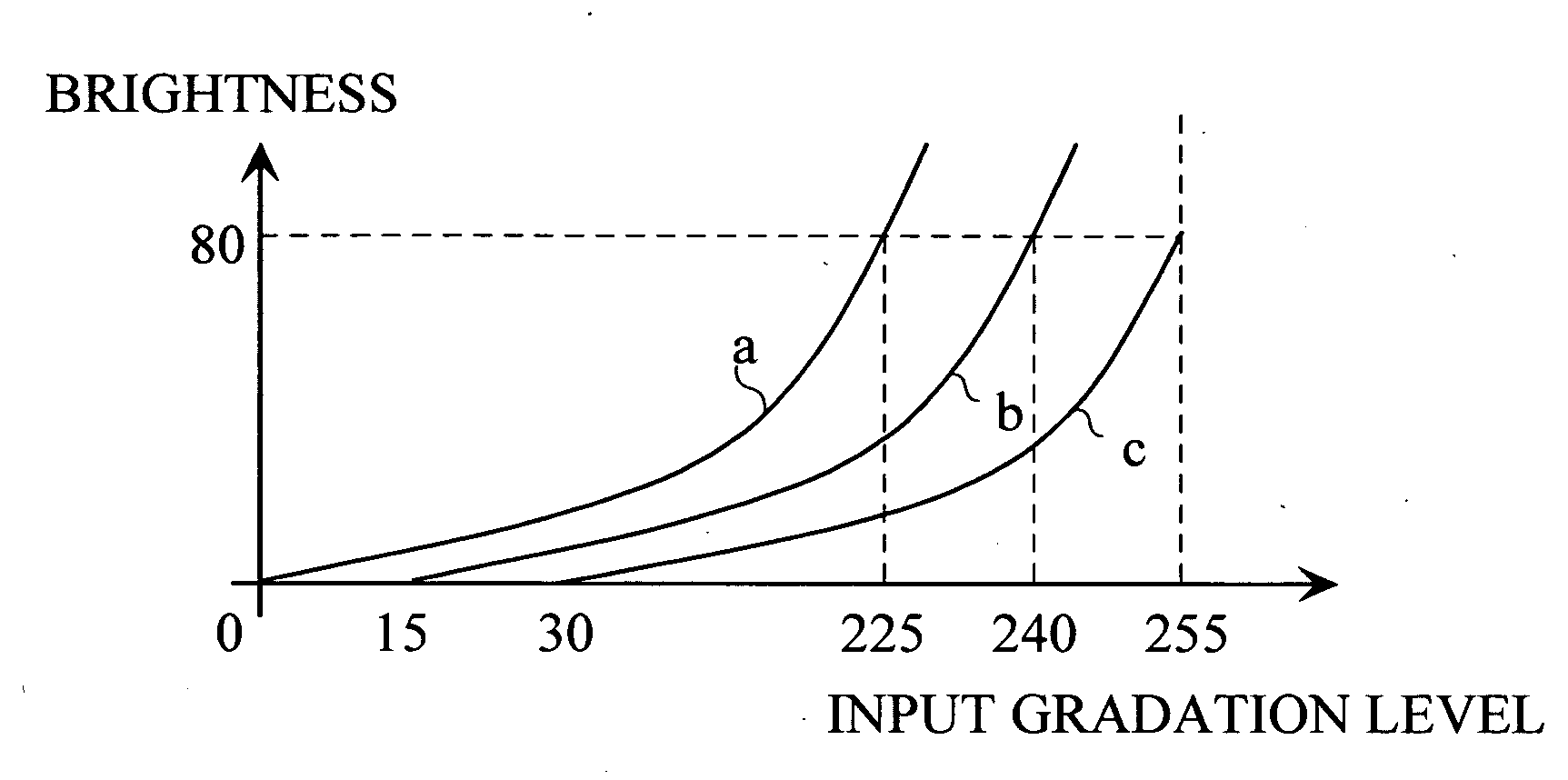
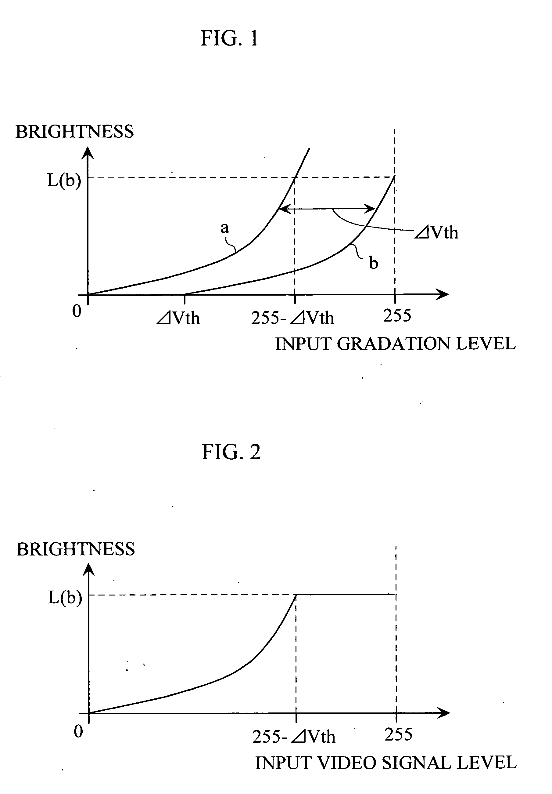
[0044] It is assumed that input gradation level-brightness characteristics of pixels a and b whose display panels differ from each other have characteristics shown by a and b of FIG. 1. When the light light-emission start voltages Vth differ from each other in the pixels as shown in FIG. 1, the uneven display is generated.

[0045] The light-emission efficiency characteristics (gamma characteristics) themselves are substantially equal to one another among the pixels. Therefore, when the input video signal level brightness characteristic of one of the two pixels is horizontally shifted by a value corresponding to the difference ΔVth in light-emission start gradation levels Vth between the pixels, the input video signal level-brightness characteristics become equal to each other at positions of the pixels a and b, which allows the uneven display to be corrected.

[0046] For example, in an...

second embodiment

[B] Description of Second Embodiment

[1] Description of Basic Concept of Second Embodiment

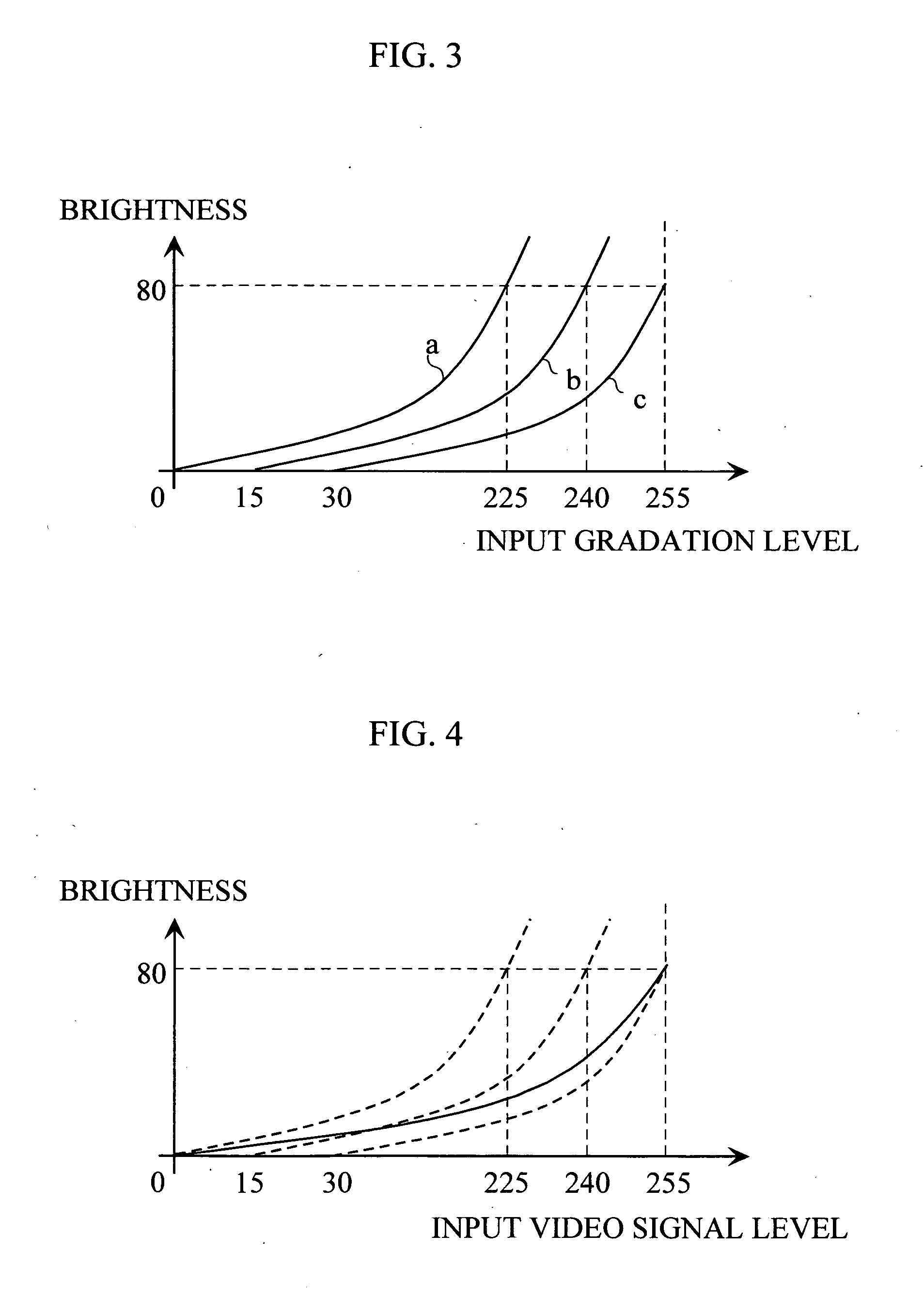
[0143] In the first embodiment, it is assumed that the light-emission efficiency characteristics themselves are equal to one another among the pixels in the display panel, and the input video signal level brightness characteristic of one of two pixels is horizontally shifted by the value according to the difference ΔVth in light-emission start gradation level Vth between the pixels. However, as shown in FIG. 18, sometimes the light-emission efficiency characteristics themselves differ from one another among the pixels in the display panel due to the various causes.

[0144]FIG. 18 shows input gradation level-brightness characteristics of the pixels a and b whose display panels differ from each other. In this case, for the sake of convenience, the input gradation level-brightness characteristics are expressed by the line, however, actually the input gradation level-brightness characteristics are ...


PUM


Abstract

An uneven display correction method including a first step of dividing a display area of a display panel into a plurality of unit areas, the first step setting one arbitrary unit area among the unit areas at a reference area, the first step previously determining a value as a correction parameter in each unit area, the value corresponding to a difference between a light-emission start gradation level of the unit area and the light-emission start gradation level of the reference area; and a second step of correcting an input video signal based on the correction parameter determined in each unit area.

Description

TECHNICAL FIELD [0001] The present invention relates to a method of correcting uneven display in display panels such as an organic EL panel. BACKGROUND ART [0002] In the display panels such as the organic EL panel, currently it is difficult that a brightness characteristic is equalized over the whole areas, and generation of the uneven display becomes a serious problem. A fluctuation in film thickness of a light-emission layer in a display panel production process can be cited as an example of the cause for the generation of the uneven display. [0003] In one of the conventional methods of correcting the uneven display, uneven display correction parameters for all the gradation levels are previously prepared in each pixel, and an input signal is corrected based on the uneven display correction parameter. In the above conventional method, it is necessary that the uneven display correction parameters for all the gradation levels are prepared in each pixel. [0004] The inventor discovere...

Claims


Application Information

Patent Timeline
IPC IPC(8): G09G5/02G09G3/20G09G3/30H05B33/14
CPCG09G3/2096G09G3/3208G09G2310/0221G09G2320/0233G09G2320/0673G09G2320/08G09G2360/147G09G2360/16
Inventor KINOSHITA, ATSUSHITANASE, SUSUMUMORI, YUKIOYAMASHITA, ATSUHIROINOUE, MASUTAKAKINOSHITA, SHIGEO
Owner SANYO ELECTRIC CO LTD
Why Eureka
Try Eureka