Optical record medium and optical record method thereof

An optical recording medium, optical recording technology, applied in the direction of optical recording carrier, optical recording/reproduction/erasing method, optical recording head, etc., capable of solving problems such as difficulties in multi-level recording

Inactive Publication Date: 2002-05-01
TDK CORPARATION
View PDF1 Cites 0 Cited by
  • Summary
  • Abstract
  • Description
  • Claims
  • Application Information

AI Technical Summary

Problems solved by technology

In practice, it is extremely difficult to perform multi-level recording with more than 5 stages by changing the laser power

Method used


Image

  • Optical record medium and optical record method thereof
  • Optical record medium and optical record method thereof
  • Optical record medium and optical record method thereof

Examples


Embodiment 1

[0078] 7-stage irradiation time was set, and the laser beams satisfying the above-mentioned conditions (1)-(3) were multi-stage recorded respectively (3 types of reference powers: 10mW, 11mW, and 12mW).

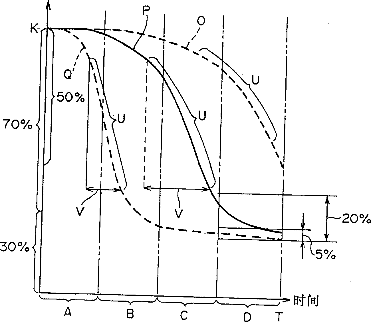
[0079] As a result, recording marks written by each reference power can be reliably read. The jitter value of this signal is also good. In addition, according to the respective reference powers, when the laser beam is irradiated to the virtual recording unit within the total permissible irradiation time, the change state of the light reflectance with the elapsed time is as follows: Figure 6 (solid lines A, B, C).

[0080] Such as Figure 6 As shown, overall the final light reflectance is reduced by more than 70% of the initial reflectance K. In addition, in the 1 / 4 section at the end of the allowable irradiation time, the change in reflectance moderately converges, and an area suitable for recording can be secured for a relatively long period of time. This is interpreted...

Embodiment 2

[0082] Set 7-stage irradiation time to record laser beams that satisfy the above conditions (1) and (3) but not (2) in multi-stage respectively (the reference power is 9mW).

[0083] As a result, recording marks written according to the reference power can be read. The jitter value is slightly worse than that of Example 1. In addition, according to the reference power, when the laser beam is irradiated to the virtual recording unit in the total permissible irradiation time, the change state of the light reflectance with the elapsed time is in Figure 6 (dotted line D).

[0084] Such as Figure 6 As shown, the final light reflectance is reduced by more than 70% of the initial reflectance K. However, the amount of change in light reflectance at the end quarter of the permitted irradiation time is large, and as a result, the irradiation time corresponding to the area suitable for recording is slightly closer to the end of the permitted irradiation time. It is presumed that th...

Embodiment 3

[0086] Set 7-stage irradiation time to record laser beams that satisfy the above conditions (1) and (2) but not (3) in multi-stage respectively (the reference power is 13 mW).

[0087] As a result, recording marks written according to each reference power can be read. The jitter value is slightly worse than that of Example 1. In addition, according to the respective reference powers, when the laser beam is irradiated to the virtual recording unit in the total permissible irradiation time, the change state of the light reflectance with the elapsed time is in Figure 6 (Double-dashed line E) indicates.

[0088] Such as Figure 6 As shown, the final light reflectance is reduced by more than 70% of the initial reflectance K. However, the amount of change in the light reflectance at the end 1 / 4 of the allowable irradiation time is small and converges relatively early. As a result, since the irradiation time corresponding to the area suitable for recording is short, it is presum...


PUM


Abstract

An optical recording medium including an optical reflective layer and a recording layer so as to record information therein, in the recording layer, a virtual recording cell having an arbitrary unit length and a unit width perpendicular to the unit length is continuously defined. In the case where the laser beam is irradiated to the virtual recording cell over the entire allowable irradiation time T securable to one virtual recording cell, a reference power of the laser beam is preset so that an optical reflectance of the virtual recording cell can be reduced more than 50% with respect to the initial reflectance. Further, the laser beam having the preset reference power is irradiated to the virtual recording cell in a state that an irradiation time is modulated into five stages or more, and thereby, a recording mark giving five stages or more different optical reflectance to the virtual recording cell can be formed. The optical recording medium having a higher improved read accuracy.

Description

technical field [0001] The present invention relates to an optical recording medium and an optical recording method thereof for recording information by forming recording marks by irradiating laser beams on a recording layer. In particular, it relates to a technique for recording data in multiple levels by forming a plurality of recording marks in different states. Background technique [0002] Compared with the original method of recording data by changing the length of the reproduced signal (the length of the reflection signal modulation part) of the original optical recording medium into a multi-level recording data, by switching the depth of the reproduction signal (modulation degree of the reflection signal) to multi-level, Studies on a method of recording a plurality of data in each signal of the same length are increasing. [0003] According to this optical recording method, since a plurality of data can be recorded in the depth direction as compared with the case of...

Claims


Application Information

Patent Timeline
Patent Type & Authority Applications(China)
IPC IPC(8): G11B7/244G11B7/0045G11B7/013G11B7/125G11B7/126G11B7/1267G11B7/24
CPCG11B7/1267G11B7/24085G11B7/24088G11B7/126G11B7/00455
Inventor 塚本修司
Owner TDK CORPARATION
Why Eureka
Try Eureka