Three dimensional effect lamp assembly

A technology of assembly and lens, applied in the field of electric lamps

Inactive Publication Date: 2008-05-28
VALEO SYLVANIA L L C
View PDF0 Cites 26 Cited by
  • Summary
  • Abstract
  • Description
  • Claims
  • Application Information

AI Technical Summary

Problems solved by technology

While it is mechanically desirable to place the lights in the bumper area, this m

Method used


Image

  • Three dimensional effect lamp assembly
  • Three dimensional effect lamp assembly
  • Three dimensional effect lamp assembly

Examples


Embodiment Construction

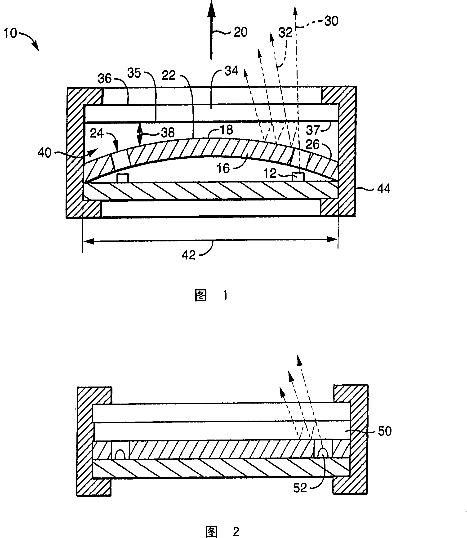
[0014] FIG. 1 shows a schematic cross-sectional view of an automotive light assembly 10 providing a three-dimensional image. The lamp assembly 10 includes at least one light source 12 , a reflector 16 and a partially reflective lens 34 .

[0015] The lamp assembly 10 includes at least one light source 12 , a reflector 16 and a partially reflective lens 34 . Although the assembly 10 can be constructed with any light source 12, it is preferred to keep the assembly 10 as thin as possible in the axial direction by using a small image light source 12, such as a small incandescent filament lamp, a small arc discharge lamp or most Small (5 mm diameter or less) LED (light emitting diode) light sources 12 are preferred. This light source 12 has a minimum image diameter, which is the smallest dimension transverse to the image projected towards the illuminated area. The light source 12 may be a white light source or a colored source. The light source(s) 12 may be suitably mounted on a...


PUM


Abstract

A lamp assembly with a thin actual dimension providing an image of greater apparent depth may be formed from a light source, reflector and a partially reflective and partially transmissive lens. The mirrored surface is oriented axially to face a field to be illuminated. A partially light reflective and partially light transmissive lens having a first surface faces the reflector. The lens is offset from the mirrored surface, thereby defining a cavity intermediate the reflector and the lens. The mirrored surface and the first surface of the lens are smoothly bowed with respect of one to the other. At least one LED (light emitting diode) light source capable of emitting visible light, is positioned near the cavity and oriented to direct light into the cavity intermediate the reflector and the lens. Because of the bowing, the multiple reflected images are offset inducing an optical illusion of depth.

Description

[0001] Cross References to Related Applications [0002] This application hereby claims the benefit of its Provisional Application Serial No. 60 / 853,877 filed on October 24, 2006 for "Tree Dimensional Effect Lamp Assembly". technical field [0003] This invention relates to electric lamps, and in particular to automotive lamps. In particular, the invention relates to automotive lamps with three-dimensional images. Background technique [0004] A description of the relevant field including information disclosed under 37 CFR 1.97 and 1.98 [0005] Exterior automotive lights typically have reflective housings that direct the emitted light in a desired direction and pattern. The shroud provides depth to the lamp image allowing for a stylized and increased image size. However, the enclosure has physical depth and must be accommodated in an adjacent engine bay, trunk, or other area of ​​the vehicle. It would be desirable if a lamp could be formed that provided a deep visual im...

Claims


Application Information

Patent Timeline
IPC IPC(8): F21V7/04F21V5/04F21V19/00F21V17/00F21S8/10F21W101/02F21W107/10
Inventor D·艾格利R·L·金B·波特
Owner VALEO SYLVANIA L L C
Why Eureka
Try Eureka