Optical element, a lighting system and a luminaire for providing a skylight appearance

a technology of optical elements and luminaires, applied in the field of optical elements, can solve the problems of limited skylight experience, complicated structure, and large application requirements, and achieve the effect of cost-effectiveness

Active Publication Date: 2014-06-12
KONINKLIJKE PHILIPS ELECTRONICS NV
View PDF4 Cites 28 Cited by
  • Summary
  • Abstract
  • Description
  • Claims
  • Application Information

AI Technical Summary

Benefits of technology

[0004]It is an object of the invention to provide a more cost

Problems solved by technology

In other words, the luminaire of the cited patent application provides a limited skylight experience.
Further, the luminaire according to the cited patent application has a complicated structure and requires a relatively large number of optical elements, such as, at least two light sources which each e

Method used


Image

  • Optical element, a lighting system and a luminaire for providing a skylight appearance
  • Optical element, a lighting system and a luminaire for providing a skylight appearance
  • Optical element, a lighting system and a luminaire for providing a skylight appearance

Examples


Embodiment Construction

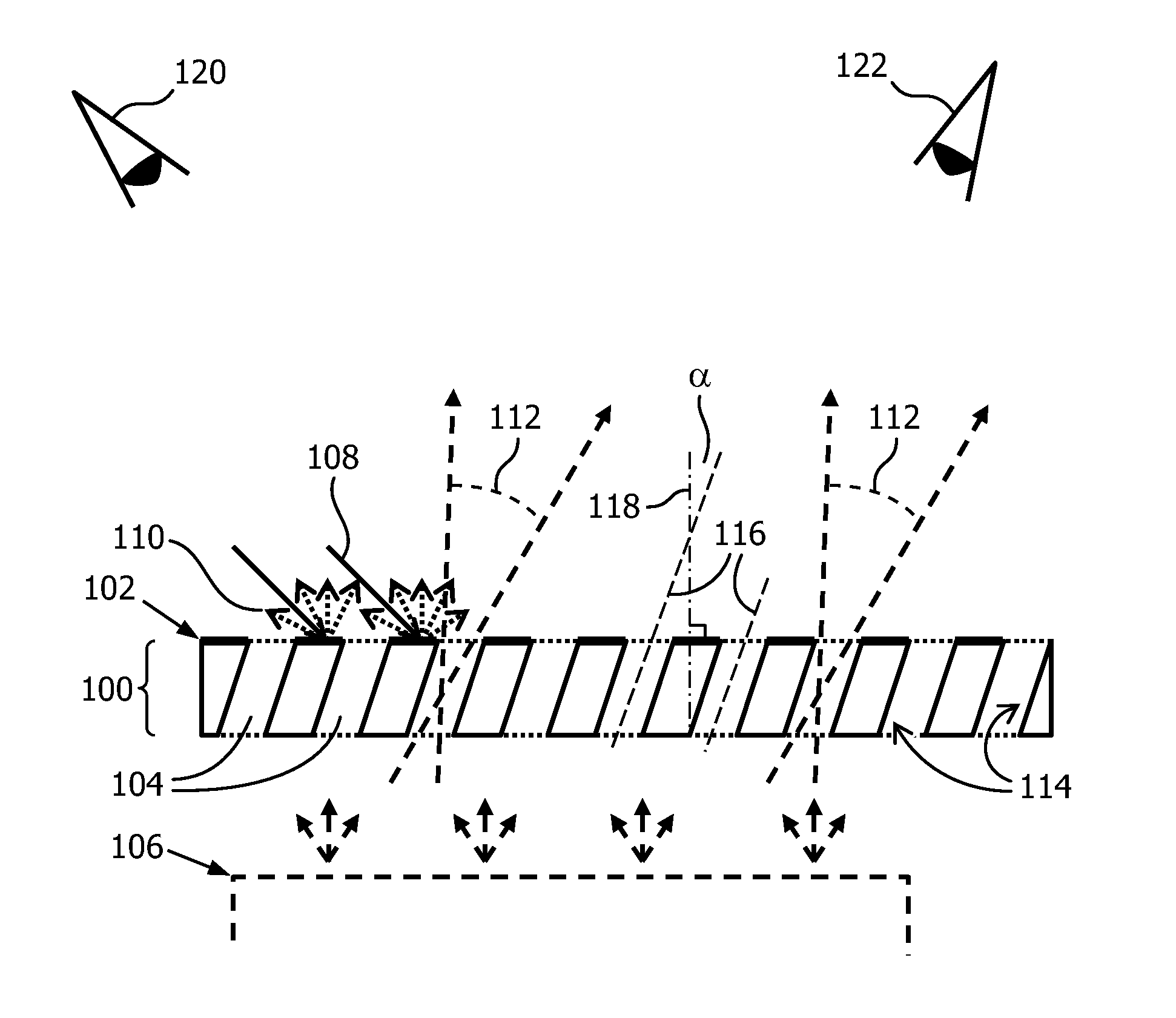
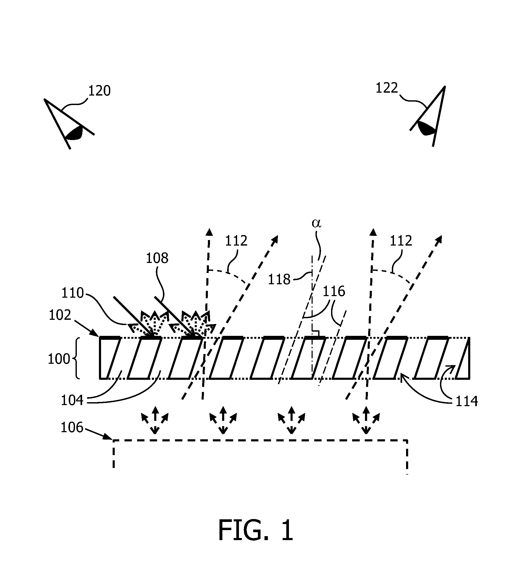
[0047]A first embodiment is shown in FIG. 1. FIG. 1 schematically presents a cross-section of an optical element according to the first aspect of the invention. The optical element comprises a plate 100 comprising a plurality of light transmitting channels 104 which act as a collimating means. The plate 100 is arranged parallel to a light emitting surface 106 of, for example, a light source with a large light emitting surface, or a lighting system which comprises a plurality of light emitters in a virtual plane.

[0048]A top surface 102 of the plate, which is a surface arranged parallel to the light emitting surface 106, is reflective in a predetermined spectral range to obtain a blue light emission. The top surface 102 is, for example, provided with a blue coating or a solid layer of a blue material. Ambient light 108 which impinges on the top surface 102 is reflected and mainly blue light 110 is reflected. If the top surface 102 is diffusely reflective, blue light is reflected in a ...


PUM


Abstract

An optical element, a lighting system and a luminaire is provided. The optical element comprises a plate 100 and a plurality of collimating means. The optical element is to be used in front of a light source comprising a light emitting surface 106, and the optical element is configured to obtain a skylight appearance. The plate 100 is to be arranged parallel to the light emitting surface 106. The plate 100 is opaque and comprises a plurality of holes 104. The plate 100 further comprises a reflective surface 102 which is to be arranged parallel to the light emitting surface 106. The reflective surface 102 is light reflective in a predetermined spectral range to obtain a blue light emission 100. The plurality of collimating means collimate a part of the light received from the light source to obtain a collimated light beam 112 in a specific direction. Each one of the collimating means comprises one of the plurality of holes of the plate 104.

Description

FIELD OF THE INVENTION[0001]The invention relates to optical elements which are used to create a skylight appearance.BACKGROUND OF THE INVENTION[0002]Published patent application US2008 / 0273323A1 discloses a specific luminaire design to emit light which is experienced by users as pleasant. The luminaire comprises a main light source and an additional light source. The additional light source emits light of a color spectrum that is different from the color spectrum of the main light source. Light of the main light source and of the additional light source are mixed before being emitted through the main light exit window of the luminaire. Further, a portion of the light emitted by the additional light source is guided to a side or a rear side of the luminaire in order to be emitted through an additional light exit window on said side or said rear side of the luminaire. Such a luminaire provides an opportunity to emit white light through the main light exit window and also to emit ligh...

Claims


Application Information

Patent Timeline
IPC IPC(8): F21V9/02
CPCF21V9/02E04B9/32E06B3/66376F21S8/04F21V11/08F21Y2115/10G02B6/005G02B6/0053G02B6/0055G02B6/0076
Inventor SEUNTIENS, PETRUS JOHANNES HENDRIKUSSALTERS, BART ANDREONAC, GABRIEL-EUGENMEERBEEK, BERENT WILLEMVAN LOENEN, EVERT JAN
Owner KONINKLIJKE PHILIPS ELECTRONICS NV
Why Eureka
Try Eureka