Method of operating an optical motion sensing device and optical motion sensing device implementing this method

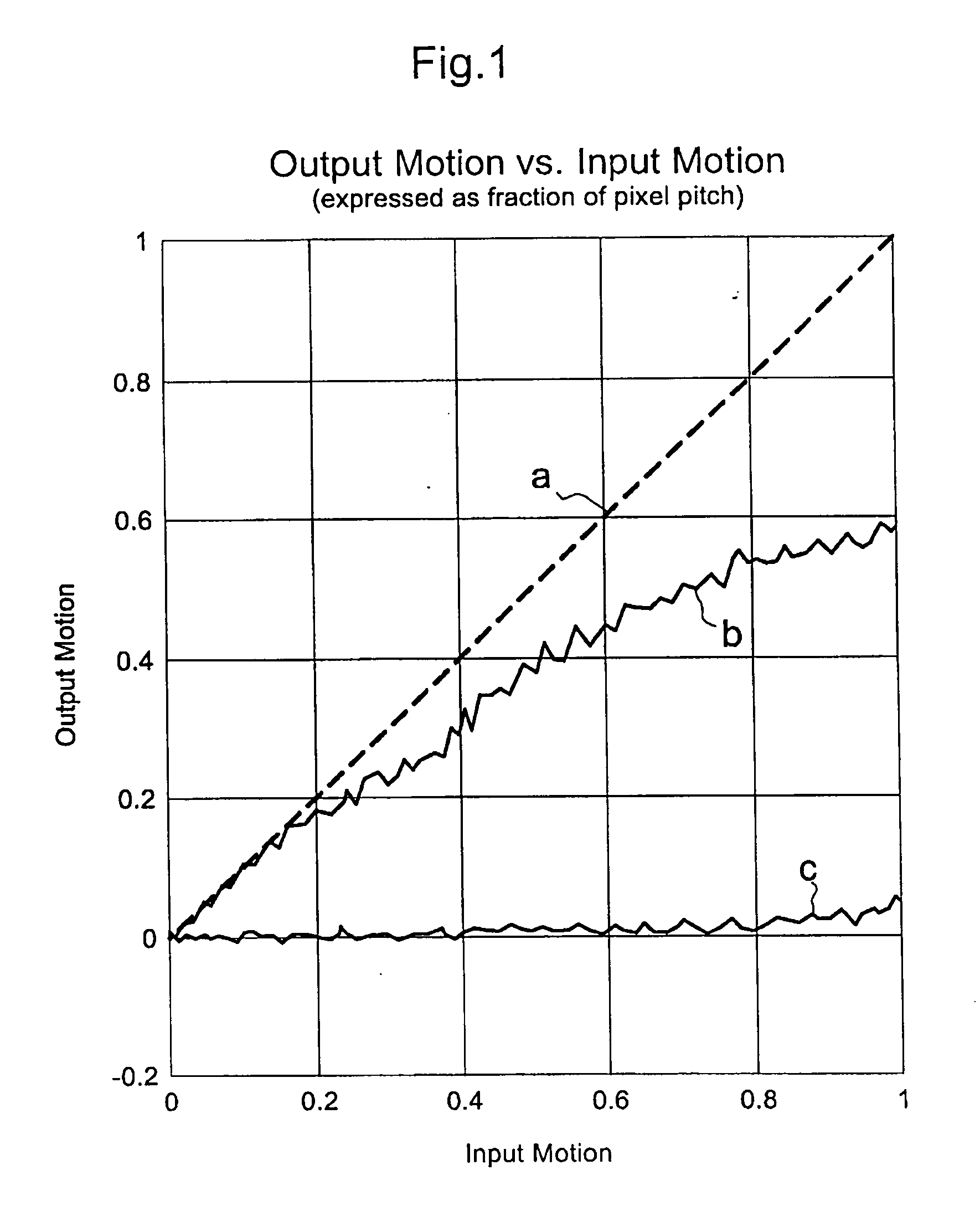
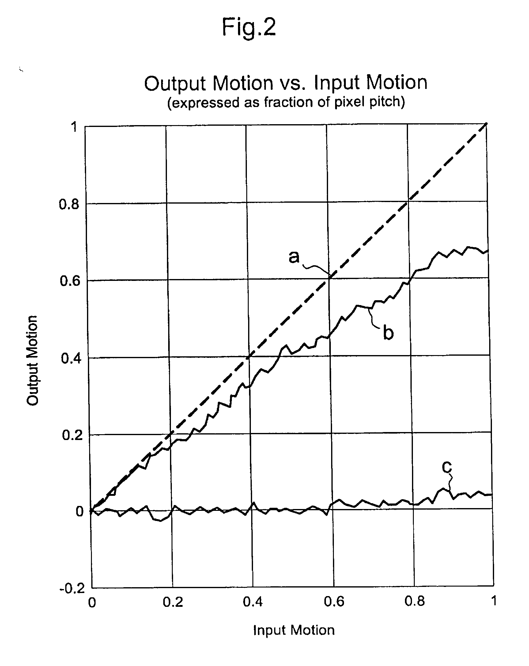
a technology of optical motion sensing and optical motion, applied in the direction of instruments, electric digital data processing, electrical apparatus, etc., can solve the problems of high unsuitability, gain on the surface, and change in the gain curve shown in fig. 1 for different surfaces

Active Publication Date: 2005-01-06
EM MICROELECTRONIC-MARIN
View PDF25 Cites 28 Cited by
  • Summary
  • Abstract
  • Description
  • Claims
  • Application Information

AI Technical Summary

Benefits of technology

[0010] According to a first aspect of the invention, there is provided a method of operating an optical motion sensing device comprising a light source and a photodetector device, the method comprising the steps of a) illuminating a surface portion with radiation by means of the light source, b) detecting radiation reflected from the illuminated surface portion by means of the photodetector device, c) detecting and measuring displacement with respect to the illuminated surface portion, ...

Problems solved by technology

This dependency is highly not desirable.
Another problem is that the gain curve shown in FIG. 1 changes fo...

Method used


Image

  • Method of operating an optical motion sensing device and optical motion sensing device implementing this method
  • Method of operating an optical motion sensing device and optical motion sensing device implementing this method
  • Method of operating an optical motion sensing device and optical motion sensing device implementing this method

Examples


Embodiment Construction

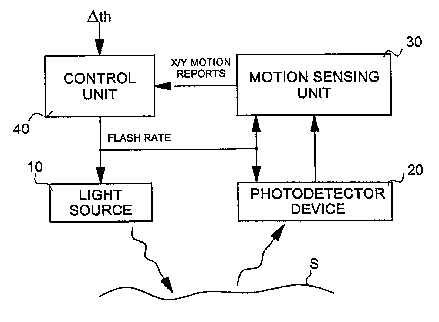
[0022]FIG. 3 illustrates the basic principle of the invention. It basically consists of an optical sensing system comprising a light source 10 for illuminating a portion of a surface S with radiation, a photodetector device 20 having at least one photosensitive element responsive to radiation reflected from the illuminated surface portion S, and a motion sensing unit 30, coupled to the output of photodetector device 20, for detecting and measuring displacement with respect to the illuminated surface portion S. During each period of activation, or flash, light source 10 is activated to illuminate the surface portion S, photodetector device 20 is activated to capture an image or intensity pattern of the illuminated surface portion S and motion sensing unit 30 is activated to detect and measure the displacement with respect to the illuminated surface portion S based on a comparison of the intensity pattern detected by photodetector device 20 and a previous intensity pattern detected by...


PUM


Abstract

There is described a method of operating an optical motion sensing device comprising a light source and a photodetector device, the method comprising the steps of a) illuminating a surface portion with radiation by means of the light source, b) detecting radiation reflected from the illuminated surface portion by means of the photodetector device, c) detecting and measuring displacement with respect to the illuminated surface portion; and d) outputting motion reports that are each representative of a magnitude of the detected displacement, steps a) to d) defining a flash period and being repeated at a selected flash rate. The method further comprises the steps of e) comparing the magnitude of the detected displacement with a determined displacement threshold, and f) increasing or decreasing the flash rate if the magnitude of the detected displacement is respectively greater or lower than the displacement threshold. There is also described an optical motion sensing device implementing this method.

Description

FIELD OF THE INVENTION [0001] The present invention generally relates to optical motion sensing devices, in particular for use in optical pointing devices. The present invention more particularly relates to a method of operating an optical motion sensing device as well as an optical motion sensing device implementing this method. BACKGROUND OF THE INVENTION [0002] Optical pointing devices are already known in the art. U.S. Pat. No. 5,288,993 for instance discloses a cursor pointing device utilizing a photodetector array and an illuminated target ball having randomly distributed speckles. U.S. Pat. No. 5,703,356 (related to the above-mentioned U.S. Pat. No. 5,288,993) further discloses (in reference to FIGS. 23A and 23B of this document) an optical cursor pointing device in the form of a mouse which does not require a ball and wherein light is reflected directly from the surface over which the pointing device is moved. [0003] In both cases, the optical pointing device includes a ligh...

Claims


Application Information

Patent Timeline
IPC IPC(8): G06F3/03G06F3/033
CPCG06F3/0317
Inventor LAUFFENBURGER, JAMES HAROLDAFRIAT, GILROTZOLL, ROBERT R.
Owner EM MICROELECTRONIC-MARIN
Why Eureka
Try Eureka