Optical coupler apparatus and method

a technology of optical couplers and optical signals, applied in the field of optical couplers, can solve the problems of high excess loss of mmi couplers, high sensitivity to waveguide width variations, and high excess loss of 22 star couplers, so as to achieve the maximum possible splitting ratio, improve the polarization and fabrication sensitivity, and improve the wavelength

Active Publication Date: 2006-09-28
RPX CORP +1
View PDF5 Cites 6 Cited by
  • Summary
  • Abstract
  • Description
  • Claims
  • Application Information

AI Technical Summary

Benefits of technology

[0010] The present invention provides a PLC coupler apparatus for coupling of optical signals with improved wavelength, polarization, and fabrication sensitivity. PLC couplers in accordance with the present invention with waveguides arranged in a curved configuration cause the coupler to have a maximum possible splitting ratio, as wavelength, polarization, or fabrication are varied, that is less

Problems solved by technology

However, MMI couplers typically exhibit undesirable excess loss, and are sensitive to waveguide-width variations that occur during PLC fabrication.
However, as with the MMI coupler, 2×2 star couplers typically exhibit high excess loss.
Asymmetric couplers, however, are highly sensitiv

Method used


Image

  • Optical coupler apparatus and method
  • Optical coupler apparatus and method
  • Optical coupler apparatus and method

Examples


Embodiment Construction

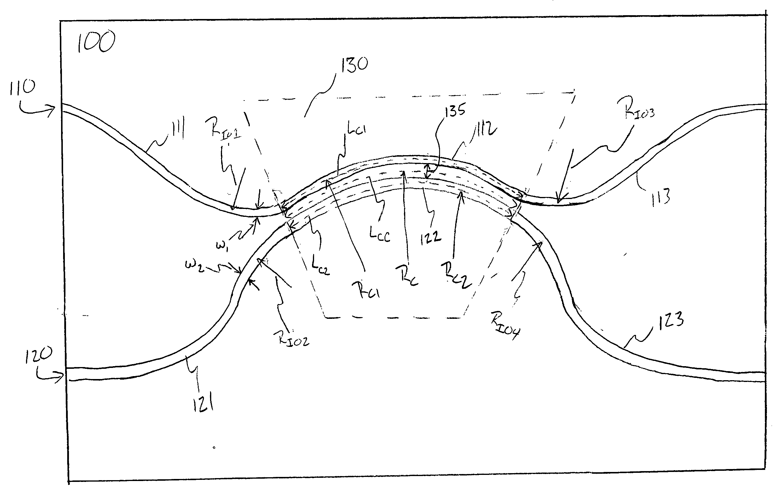
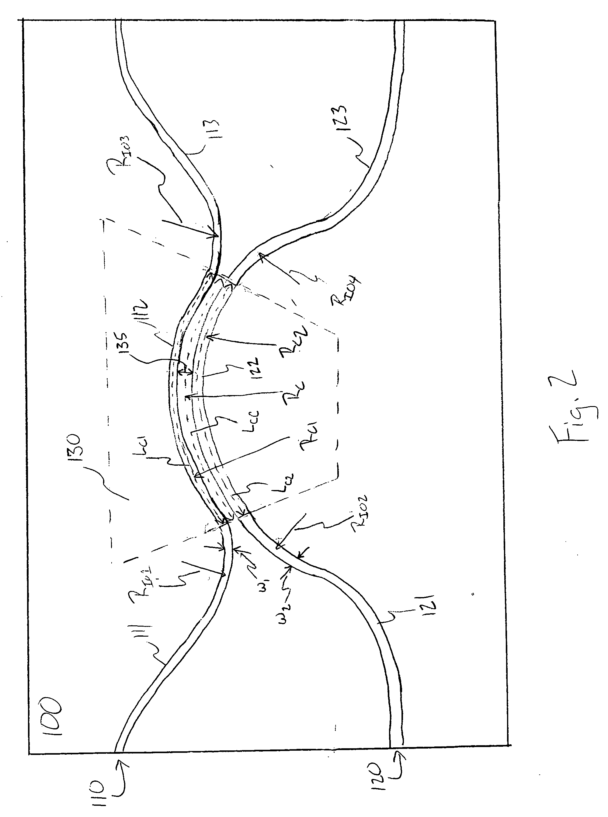
[0020]FIG. 2 is an illustration of one embodiment of a PLC coupler 100 according to the invention. The PLC coupler 100 preferably comprises a first waveguide 110 and a second waveguide 120. Each of the first and second waveguides 110, 120 include an input portion 111, 121, a curved coupling portion 112, 122 in a coupling region 130, and an output portion 113, 123, respectively.

[0021] The input and output portions 111, 121, 113, 123 of the first and second waveguides preferably have radii of curvature Rio1, Rio2, Rio3, Rio4, (or “bend radii”) that are substantially the smallest possible without creating significant bend radiation loss to minimize contributions to the coupling from the input / output waveguides 111, 121, 113, 123.

[0022] The curved coupling portions 112, 122 of the first and second waveguides 110, 120 are operatively coupled (e.g. placed in close proximity) in the coupling region 130 such that light in the first or second waveguides 110, 120 couples between the wavegui...


PUM


Abstract

A planar lightwave circuit coupler including first and second waveguides with curved coupling portions having radii of curvature selected such that the coupler has a splitting ratio that is substantially wavelength and polarization insensitive.

Description

BACKGROUND OF THE INVENTION [0001] 1. Field of the Invention [0002] The present invention relates generally to methods and apparatus for coupling optical signals, and more particularly planar lightwave circuit (PLC) couplers with improved wavelength and polarization sensitivity. [0003] 2. Description of Related Art [0004] Optical couplers are employed in a variety of planar lightwave circuits (PLCs), including, for example, Mach-Zehnder interferometer (MZI) based switches, MZI based filters, taps, etc. The lowest-loss 2×2 coupler is a directional coupler (shown in FIG. 1(a), also called an evanescent coupler), which includes two waveguides arranged in close proximity to allow coupling of light between the waveguides. The splitting ratio of the conventional directional coupler, however, is highly sensitive to: 1) the wavelength of the light propagated through the coupler, 2) the polarization of such light, and 3) variations in the PLC coupler structure (e.g. waveguide width) which ca...

Claims


Application Information

Patent Timeline
IPC IPC(8): G02B6/26G02B6/42
CPCG02B6/12007G02B6/125G02B2006/12147
Inventor DOERR, CHRISTOPHER RICHARD
Owner RPX CORP
Why Eureka
Try Eureka