Interference filter for non-zero angle of incidence spectroscopy

a technology of interference filter and incidence spectroscopy, which is applied in the field of interference filter for non-zero angle incidence spectroscopy, can solve the problems of insufficient performance of filter, fatal to the operation of the system in which it is utilized, and real filters have some amount of transmission loss, so as to improve the performance characteristics and improve the polarization splitting

Active Publication Date: 2015-02-17
IDEX HEALTH & SCI
View PDF85 Cites 22 Cited by
  • Summary
  • Abstract
  • Description
  • Claims
  • Application Information

AI Technical Summary

Benefits of technology

[0048]The present disclosure provides optical interference filters that are suitable, for example, for use in Raman spectroscopy, fluorescence imaging, and / or quantification applications. Among other things, these filters exhibit substantially better performance characteristics when operated at about 45° angle of incidence, relative to prior known interference filters. In particular, the present disclosure provides optical filters that exhibit at least one of improved polarization splitting, edge steepness, passband bandwidth, and blocking, relative to prior known interference filters.

Problems solved by technology

Thus, failure or inadequate performance of these filters can be fatal to operation of a system in which they are utilized.
Similarly, while an ideal edge filter transmits all light in the transmission region (transmission T=1), real filters have some amount of transmission loss, invariably blocking a small portion of the light to be transmitted (T<1).
Without such filtering, the Rayleigh scattered light will swamp the detector, and may excite spurious Raman scattering in the collection path.
Conventional filters, however, exhibit narrow blocking or transmission bands that exhibit a level of transmission and / or blocking that is less than optimum.
Conventional filters that achieve high OD values at certain wavelengths or wavelength regions may not necessarily also achieve high transmission (in excess of 50%, for example) at any other wavelengths or wavelength regions.
These higher-order stopbands are one reason why it is difficult to achieve high transmission at wavelengths shorter than those over which high blocking occurs.
However, as described above and shown in FIG. 4, traditional dichroic filters exhibit substantial polarization splitting, particularly when operated at about 45° Angle of incidence.
This difference in shift ultimately offsets the filter spectra corresponding to these differing polarizations, resulting in polarization splitting.
However, in the context of edge filters and beamsplitter optical filters, polarization splitting severely limits the edge steepness of light having average polarization.
However, this method has significant limitations when used to create dichroic filters.
In addition, it has been shown that decreasing stopband bandwidth can result in a corresponding decrease in polarization splitting.
However, while this method is effective, small mismatch always results in a filter having a narrow blocking region and lower blocking level, which is often not acceptable.
As a result, the performance of a traditional dichroic filter based on a second order stopband is typically limited by the maximum coating thickness allowed by the manufacturing process.
While prior known interference filters are useful for many applications, they generally exhibit unsatisfactory characteristics when operated at about 45° angle of incidence.
However, this filter exhibits a relative passband bandwidth of only about 30%, which is unsatisfactory.
Further, this filter exhibits relatively poor edge steepness of 1.26% at one edge of stopband 62, and 0.79% at one edge of stopband 64, which are insufficient for many applications.
Accordingly, these types of filters exhibit significant limitations when used in many optical measurement techniques.

Method used


Image

  • Interference filter for non-zero angle of incidence spectroscopy
  • Interference filter for non-zero angle of incidence spectroscopy
  • Interference filter for non-zero angle of incidence spectroscopy

Examples


examples 1 and 2

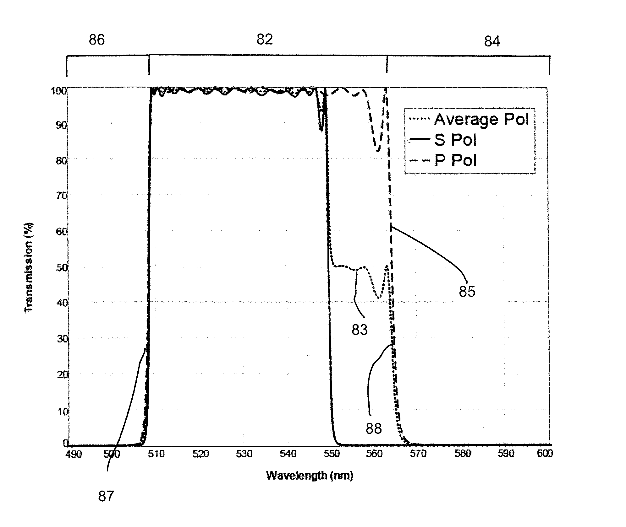
Minimal Polarization Splitting, Long Wave Pass Steep Edge Dichroic Filter Configurations Based on the Concept of Passband Defect

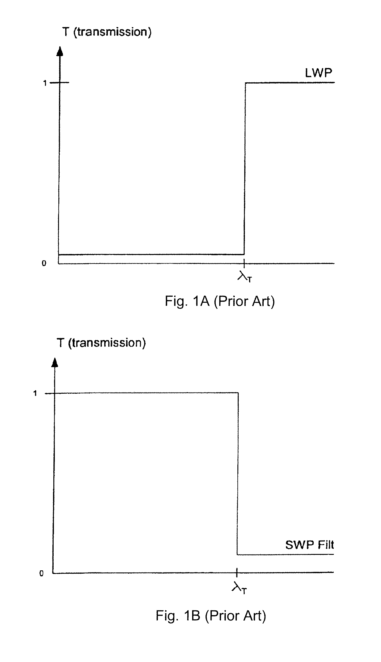
[0121]A filter design corresponding to minimal polarization long wave pass steep edge dichroic filter based on the concept of passband defect was produced by optimizing a traditional dichroic short wave pass (SWP) filter spectrum and structure against a design spectrum using well-known optimization algorithms (e.g., the variable metric approach). That is, this design was optimized starting from a dichroic SWP filter comprising a substrate and approximately 150 alternating quarter wavelength thick layers of materials having high and low refractive index at a reference wavelength, respectively, and in view of a target (design) spectrum having desired spectral characteristics.

[0122]In the design spectrum, the edge of the SWP was chosen to be slightly longer than a specified long wavelength edge of the dichroic passband. The passband ripple of the design spectr...

examples 3 and 4

532 nm Steep Dichroic Beamsplitter

[0129]A first 532 nm dichroic beamsplitter optical filter (example 3) was produced having the configuration shown in the following table:

[0130]

TABLE 3Design structure of a 532 nm steep dichroic beamsplitter532 nm Steep Dichroic BeamsplitterCoating Thickness (μm): 14.572006282Total Layers: 92LayerMaterialThickness (nm) 1Nb2O515.76397 2SiO2299.964436 3Nb2O5140.250246 4SiO2191.877075 5Nb2O5127.915529 6SiO2182.984338 7Nb2O5127.387605 8SiO2179.120336 9Nb2O5127.71754210SiO2175.63288811Nb2O5128.59222412SiO2176.38058613Nb2O5128.37391614SiO2178.88728315Nb2O5127.76939916SiO2184.19487817Nb2O5127.9342618SiO2188.22730819Nb2O5128.00575620SiO2188.05713421Nb2O5127.91821622SiO2184.47532123Nb2O5128.07298324SiO2179.42554625 Nb2O5128.14155726 SiO2176.96435527 Nb2O5 127.9697428 SiO2177.50607829 Nb2O5 126.51160430 SiO2178.3360631 Nb2O5122.57701832 SiO2184.03901133 Nb2O5 117.33583734 SiO2194.18907635 Nb2O5 112.22888736 SiO2203.6049937 Nb2O5 106.36272138 SiO2211.47630739 N...

examples 5-7

785 nm Steep Dichroic Beamsplitter

[0137]A 785 nm dichroic beamsplitter optical filter design was produced having the configuration shown in the following table.

[0138]

TABLE 5structure of a 785 nm dichroic beamsplitter785 nm Steep Dichroic BeamsplitterCoating Thickness (μm): 22.027679258Total Layers: 102LayerMaterialThickness (nm) 1Nb2O532.65508 2SiO2144.868199 3Nb2O547.804313 4SiO2128.394549 5Nb2O5238.282792 6SiO2278.529226 7Nb2O5205.569093 8SiO2192.698961 9Nb2O5213.37000410SiO2229.79832411Nb2O5202.3180412SiO2229.54052813Nb2O5188.95296914SiO2264.18647715Nb2O5166.66879716 SiO2298.76361117 Nb2O5151.80093718 SiO2306.54067119 Nb2O5153.74393920 SiO2292.51953821 Nb2O5167.7765422 SiO2265.66501323 Nb2O5181.80545224 SiO2248.08595425 Nb2O5186.58791626 SiO2257.08303527 Nb2O5173.73124928 SiO2282.19076329 Nb2O5159.39777130 SiO2300.39195331 Nb2O5150.9652632 SiO2297.93649533 Nb2O5162.27664734 SiO2278.17171935 Nb2O5176.66888936 SiO2253.86304537 Nb2O5184.79206838 SiO2254.29953539 Nb2O5177.74686140 Si...


PUM


Abstract

The present disclosure relates to thin film optical interference filters. The filters include a substrate and a plurality of alternating material layers deposited on the substrate. When operated at about 45° angle of incidence, the filters exhibit at least one of improved polarization splitting, edge steepness, bandpass bandwidth, and blocking, relative to conventional thin film interference filters.

Description

[0001]This application claims priority to U.S. Provisional Application No. 60 / 940,701, filed May 30, 2007, the contents of which are incorporated herein by reference.[0002]The present disclosure relates to optical thin-film interference filters, including filters suitable for use in non-zero angle of incidence spectroscopy. The present disclosure also relates to spectroscopy systems including such filters, and methods for making such filters.BACKGROUND OF THE DISCLOSURE[0003]Thin film interference filters are important components in systems for optical measurement and analysis, such as Raman spectroscopy and fluorescence microscopy. In particular, thin film interference filters, such as optical edge filters, notch filters, and / or laser line filters (LLF's), are advantageously used in such systems to block unwanted light that would otherwise constitute or generate spurious optical signals and swamp the signals to be detected and analyzed. Thus, failure or inadequate performance of th...

Claims


Application Information

Patent Timeline
Patent Type & Authority Patents(United States)
IPC IPC(8): G02B1/10G02B5/28
CPCG02B5/28G02B5/288
Inventor ERDOGAN, TURANWANG, LIGANG
Owner IDEX HEALTH & SCI
Why Eureka
Try Eureka