Method for focusing by using a pre-flash

a pre-flash and flash technology, applied in the field of automatic focusing methods, can solve the problems of poor portability of conventional cameras or analogue camcorders, easy loss of focus of conventional digital cameras operating in a dark environment or insufficient indoor light, etc., and achieve the effect of improving focusing accuracy

Inactive Publication Date: 2006-09-28
COMPAL ELECTRONICS INC
View PDF6 Cites 13 Cited by
  • Summary
  • Abstract
  • Description
  • Claims
  • Application Information

AI Technical Summary

Benefits of technology

[0008] In view of the above, an object of the present invention is to provide a method for focusing by using a pre-flash for enhancing focusing accuracy without adding extra devices.
[0009] Another object of the present invention is to provide a method for focusing by using a pre-flash for shortening focus adjusting time and saving power.
[0014] Instead of adding extra expensive auxiliary focusing module or modifying the original system structure with extra budget, the present invention employs the pre-flash function to obtain the distant D to the object to be photographed, by which the image sensor can improve the focusing accuracy to measure the distance to the object to be photographed under insufficient indoor light for capturing a clear image.

Problems solved by technology

Nowadays, the technology of digital cameras and digital camcorders is ever-developing, and the conventional disadvantages such as complicated operation and poor portability in the conventional cameras or analogue camcorders are improved.
Also, without auxiliary focusing system to measure the distance, a conventional digital camera operating in a dark environment or insufficient light in the indoors could easily lose focus when using only the brightness data obtained from the image sensor.
Unfortunately, such high-end digital cameras are rather costly.
Nevertheless, the red-eye-reduction means is only adapted to short-distance shots for facial expression.
And whenever the red-eye-reduction means flashes, the auto-focus module would finely adjust the focus, sometimes even up to four or five times, which is time consuming and power wasting.

Method used


Image

  • Method for focusing by using a pre-flash
  • Method for focusing by using a pre-flash
  • Method for focusing by using a pre-flash

Examples


Embodiment Construction

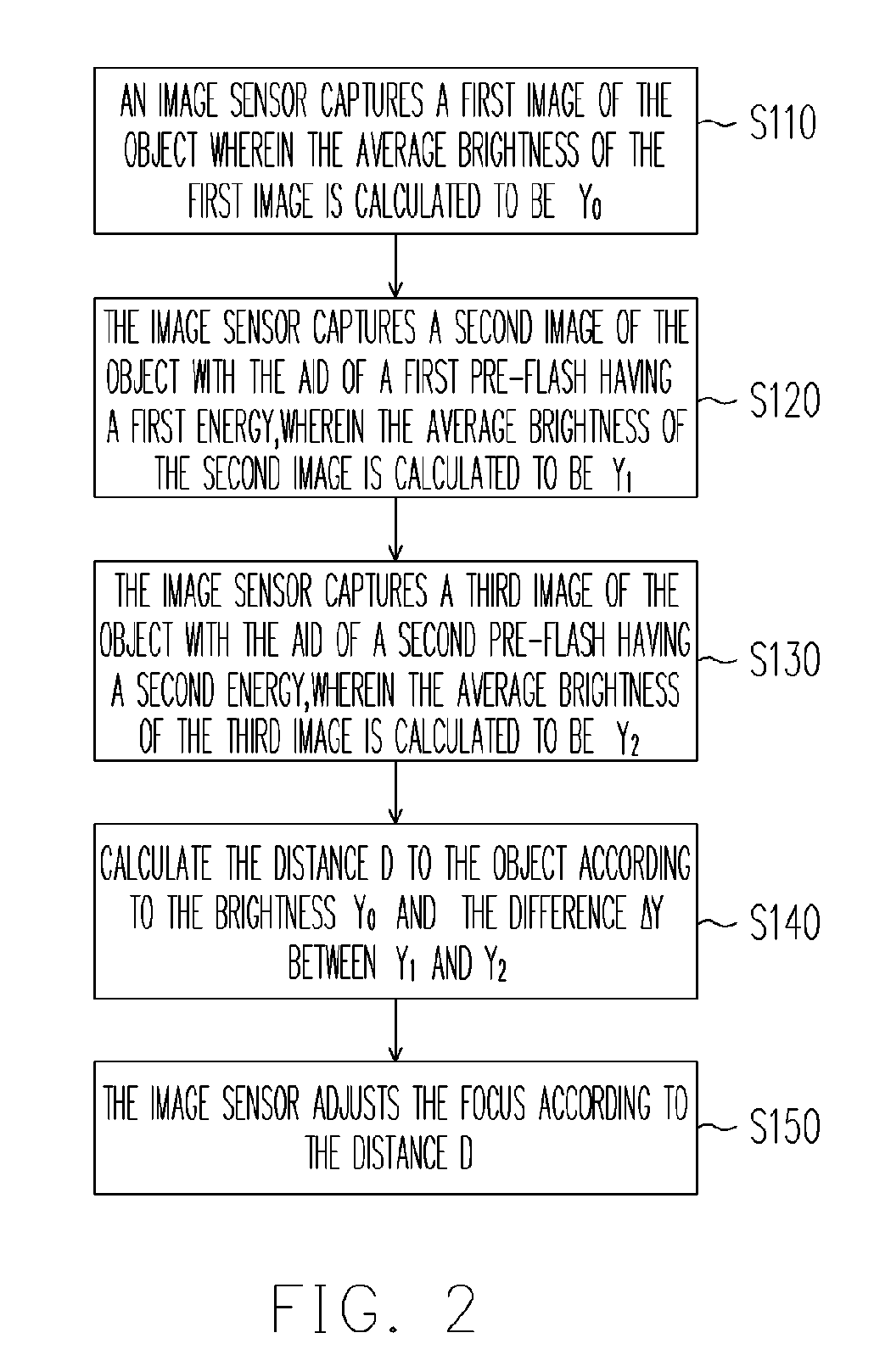
[0020] According to an embodiment of a method for focusing by using a pre-flash of the present invention, Y0 is preferred to be smaller than a predetermined minimum YL. According to the embodiment of the method for focusing by using a pre-flash of the present invention, the first energy is preferred to be substantially unequal to the second energy. According to the embodiment of the method for focusing by using a pre-flash of the present invention, the distance D to the object corresponding to Y0 and ΔY can be obtained by either checking a conversion table, or calculating from an equation. It is more preferred that the conversion table or the equation is obtained from previously collected experiment data. According to the embodiment of the method for focusing by using a pre-flash of the present invention, the distance D to the object is preferred to be obtained from Y0, ΔY and the reflection ratio R. Preferably, the relationship between the Y0, ΔY, the reflection ratio R and the dis...


PUM


Abstract

A method for focusing by using a pre-flash is provided. The method includes the following steps. First, the image sensor captures a first image of the object, wherein the average brightness of the first image is calculated to be Y0. Next, the image sensor captures a second image of the object with the aid of a first pre-flash having a first energy, wherein the average brightness of the second image is calculated to be Y1. Afterwards, the image sensor captures a third image of the object with the aid of a second pre-flash having a second energy, wherein the average brightness of the third image is calculated to be Y2. Then, the distance D to the object is calculated according to the brightness Y0 and the difference ΔY between Y1 and Y2. Finally, the image sensor adjusts the focus according to the distance D.

Description

CROSS-REFERENCE TO RELATED APPLICATION [0001] This application claims the priority benefit of Taiwan application serial no. 94108738, filed on Mar. 22, 2005. All disclosure of the Taiwan application is incorporated herein by reference. BACKGROUND OF THE INVENTION [0002] 1. Field of the Invention [0003] The present invention relates to an automatic focusing method, and particularly to a method for focusing by using a pre-flash. [0004] 2. Description of Related Art [0005] Nowadays, the technology of digital cameras and digital camcorders is ever-developing, and the conventional disadvantages such as complicated operation and poor portability in the conventional cameras or analogue camcorders are improved. Nearly all the recent digital cameras have built-in auto-focus mode and multiple manual focus modes provided for the users to properly focus the object. Also, without auxiliary focusing system to measure the distance, a conventional digital camera operating in a dark environment or i...

Claims


Application Information

Patent Timeline
Patent Type & Authority Applications(United States)
IPC IPC(8): G03B13/00
CPCG03B13/20G03B15/05H04N5/23212G03B2215/05H04N23/671
Inventor KUO, LEE-RENLIN, JIAN-YUCHANG, FENG-CHI
Owner COMPAL ELECTRONICS INC
Why Eureka
Try Eureka