Easy to open ring binder mechanism

Inactive Publication Date: 2006-09-28
HONG KONG STATIONERY MFG
View PDF15 Cites 1 Cited by
  • Summary
  • Abstract
  • Description
  • Claims
  • Application Information

AI Technical Summary

Benefits of technology

[0008] An object of the invention is to reduce the opening force of a

Problems solved by technology

Single-trigger constructions, which do exist, may not provide satisfactory opening operation without the helper springs described herein.
A disadvantage of conventional ring binder mechanisms is that they are noisy, as every student knows.
The combined loud reports of a classroomful of ring binders with the mechanisms being snapped open or shut at the beginning or end of a lecture

Method used


Image

  • Easy to open ring binder mechanism
  • Easy to open ring binder mechanism
  • Easy to open ring binder mechanism

Examples


Embodiment Construction

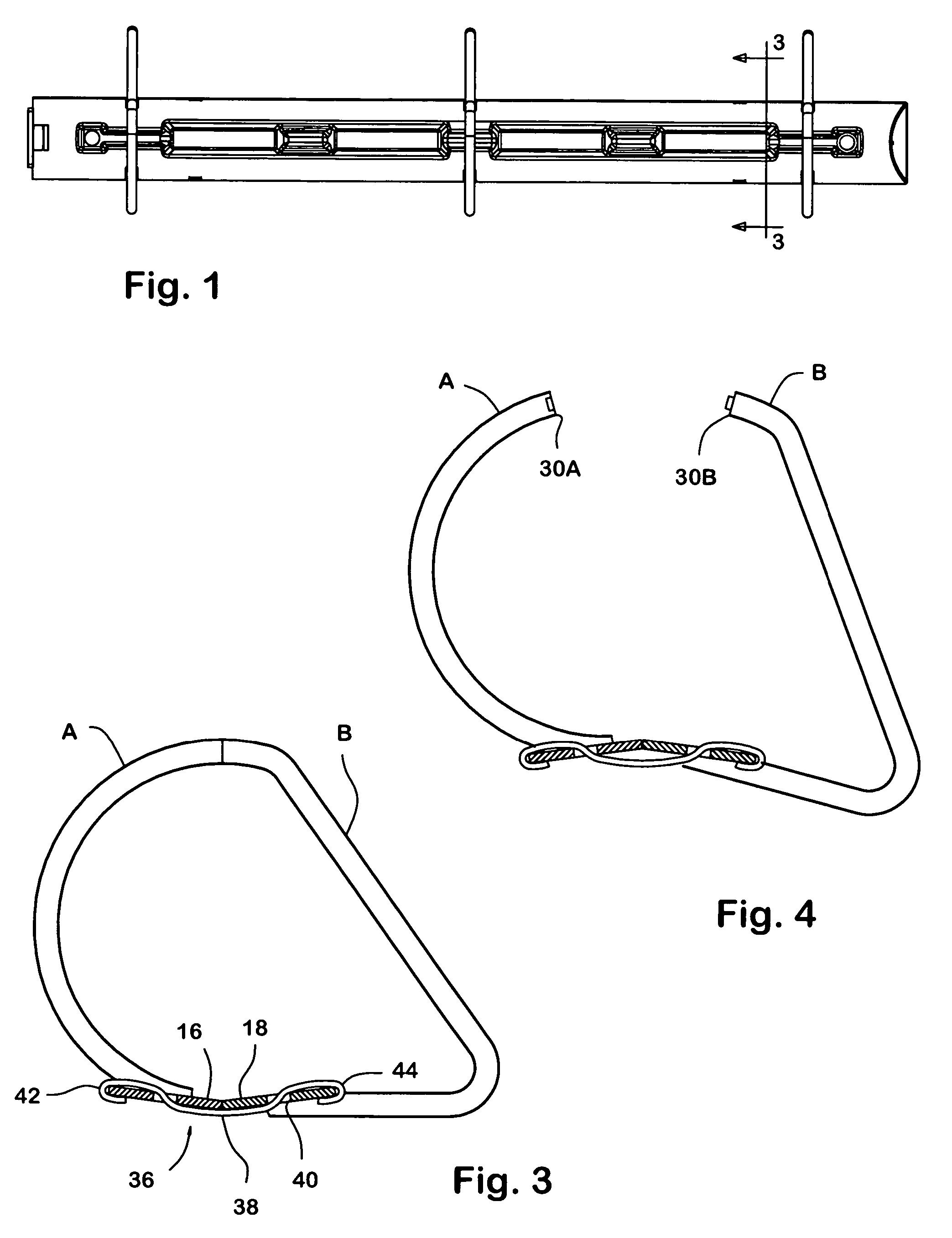
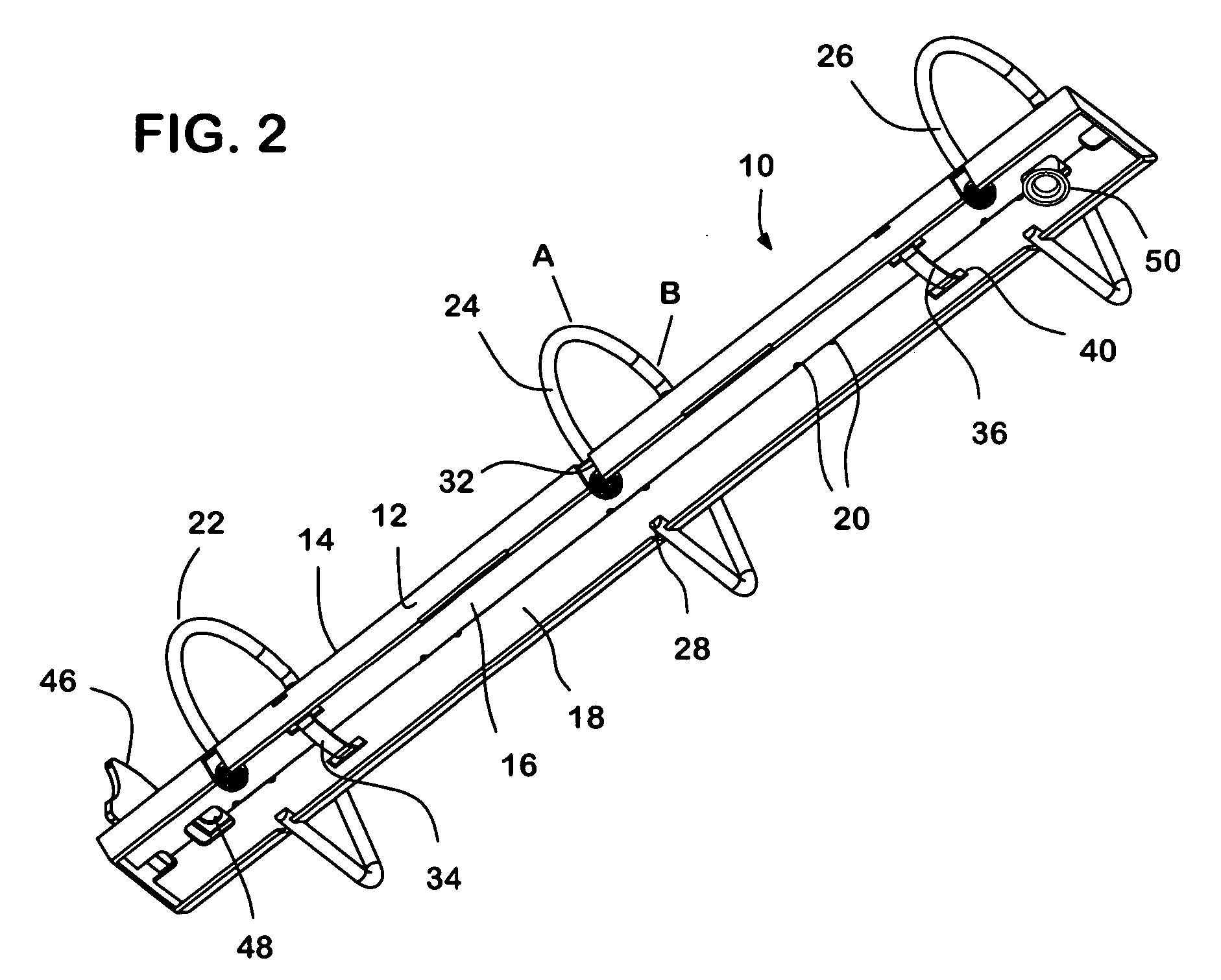
[0017]FIGS. 1 and 2 show a metal ring binder mechanism embodying the invention comprises a sheet metal spine 10 having a generally convex upper surface. The illustrated decorative embossing of the spine reinforces it somewhat, but is not important to this invention. The lateral edges 12 of the spine are bent inward toward one another along bend lines 14 so as to define seats which support the outer edges of a pair of flat sheet metal blades 16, 18. The inner edges of the blades are held in alignment by alternating swaged tabs 20. Three rings 22, 24, 26, each formed in two halves A,B, are supported by the blades, one end 28 of each ring half being rigidly affixed to a respective blade, as by welding or swaging. The tips 30A, 30B (FIG. 4) of the ring halves have features, such as a pin and socket or sinusoidal serrations, which mesh when the rings are closed to maintain alignment of the tips.

[0018] The upward (opening) movement of the blades is stopped by contact between the inner ed...


PUM


Abstract

The ease with which a metal ring binder mechanism can be opened is improved by adding at least one auxiliary helper spring for reducing the spring force applied by the spine to the blades which support the rings, so as to decrease the force required to open the rings, without affecting the page-retaining power of the binder mechanism.

Description

BACKGROUND OF THE INVENTION [0001] This invention relates to an easy to open ring binder mechanism. [0002] The most common type of ring binder mechanism intended for notebooks comprises three rings, each made in two halves. The lower end of each ring half is permanently connected to one of two blades which are held in compression, edge-to-edge, within a curved spine made of sheet metal. The blades toggle between a lowered position, in which the rings are closed, and a raised position, where the rings are open. A lever or trigger is usually installed at one or both ends of the spine, to assist a user in opening the rings, or in locking them closed. [0003] In most ring binder mechanisms, the spine flexes as the rings are moved, and this flexure provides the only spring force that holds the rings in their closed and open positions. With this arrangement, the combined width of the blades, in the open or closed positions (see FIGS. 3 and 4) is somewhat greater than the distance between t...

Claims


Application Information

Patent Timeline
IPC IPC(8): B42F13/20
CPCB42F13/26
Inventor LAM, WANG YIP
Owner HONG KONG STATIONERY MFG
Why Eureka
Try Eureka