
Electrical connector capable of interrupting an ESD path

Inactive Publication Date: 2006-09-28
AVISION
View PDF13 Cites 0 Cited by
  • Summary
  • Abstract
  • Description
  • Claims
  • Application Information

AI Technical Summary

Benefits of technology

[0007] It is therefore an object of the invention to provide an electrical connector using an insulation medium to interrupt an ESD (ElectroStatic Discharge) path so as to achieve the ESD protection in a low-cost and effective manner.
[0009] Thus, when the electrical connector is screwed to a circuit board tightly, the insulation medium can fill a gap between the column and the through hole so as to interrupt the ESD path.

Problems solved by technology

Thus, the electrostatic charges may interfere with the signal transmission of the electrical connector.
These ESD protection methods need a good electrostatic charge canalling path, and the ESD damage may occur if an improper contact exists.

Method used


Image

  • Electrical connector capable of interrupting an ESD path
  • Electrical connector capable of interrupting an ESD path
  • Electrical connector capable of interrupting an ESD path

Examples


first embodiment

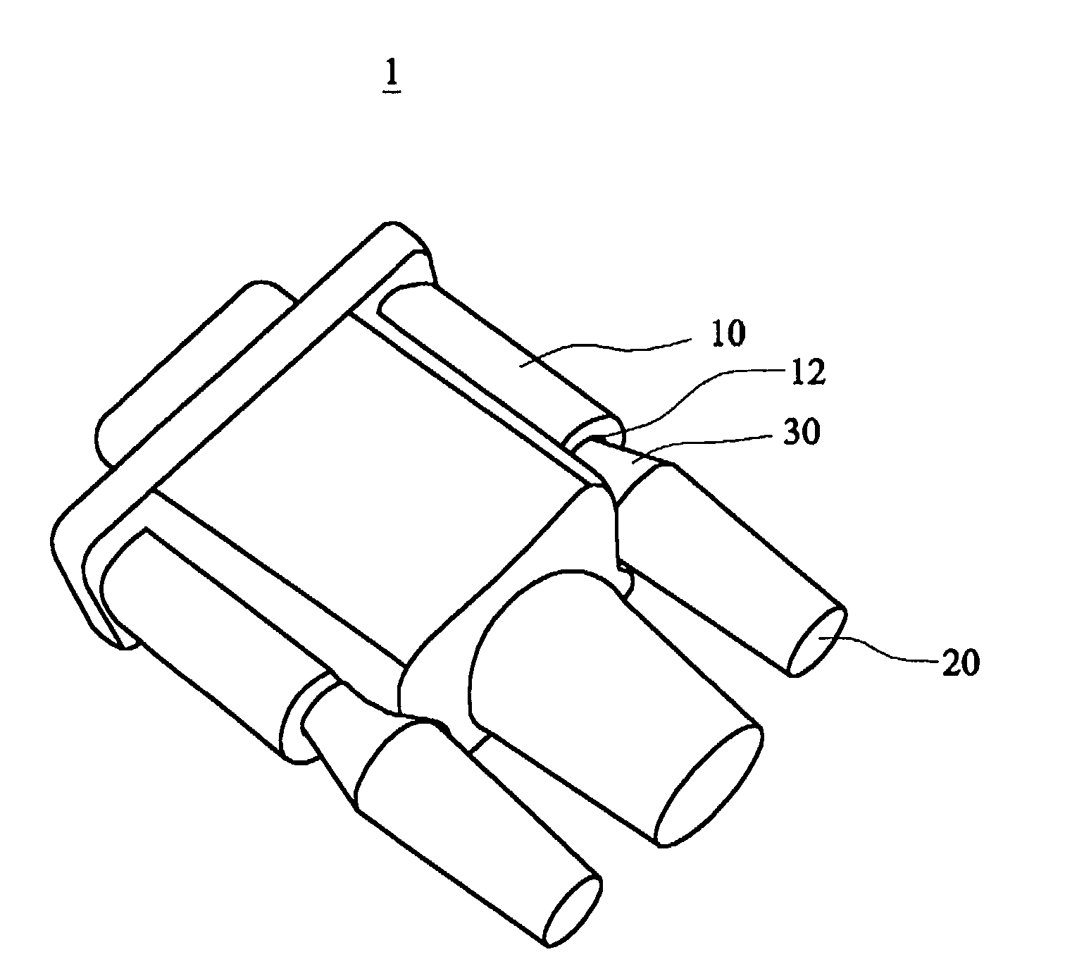
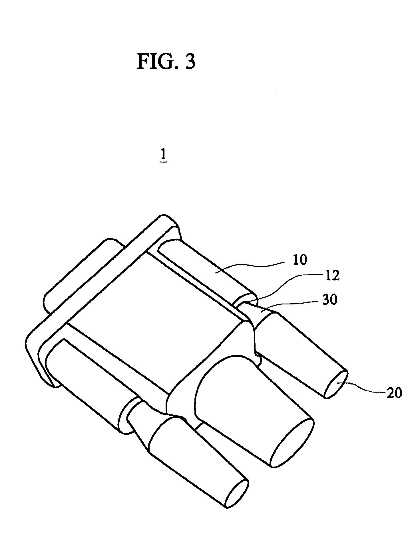
[0017]FIG. 3 is a pictorial view showing an electrical connector 1 according to the invention. FIG. 4 is a side view showing the connector of FIG. 3. Referring to FIGS. 3 and 4, the electrical connector 1 of this embodiment capable of interrupting an ESD (ElectroStatic Discharge) path is to be electrically connected to an electrical apparatus and includes a body 10, a column 20 and an insulation medium 30. The electrical apparatus may be, for example, a computer, a scanner, a multi-function peripheral, or the like. The body 10 has a through hole 12. The through hole 12 has a first part 12A with a first inner diameter and a second part 12B with a second inner diameter smaller than the first inner diameter. The first and second parts 12A and 12B respectively accommodate the column 20 with a smaller outer diameter and the insulation medium 30, which encapsulates the column 20 and has a larger outer diameter. The first part 12A may conveniently guide the column 20 to pass through the th...

third embodiment

[0020]FIG. 6 is a side view showing an electrical connector 20″ according to the invention. As shown in FIG. 6, the column 20″ of this embodiment is a tapered column, and an insulation medium 30″ is only an encapsulating layer without losing the effect of interrupting the ESD path. Thus, the column 20″ may be regarded as a first section 20A″ with a first outer diameter and a second section 20B″ with a second outer diameter smaller that the first outer diameter, and the insulation medium 30″ encapsulates the first section 20A″ and the second section 20B″.

[0021]FIG. 7 is a side view showing an electrical connector 20′″ according to a fourth embodiment of the invention. As shown in FIG. 7, this embodiment is similar to the second embodiment except that the column 20′″ is a ladder-like column and an insulation medium 30′″ is only an encapsulating layer without losing the effect of interrupting the ESD path. Thus, the column 20′″ may be regarded as a first section 20A′″ with a first oute...


PUM


Abstract

An electrical connector, which is to be electrically connected to an electrical apparatus and capable of interrupting an ESD path, includes a body, a column and an insulation medium. The body has a through hole. The column passes through the through hole. The invention utilizes the insulation medium to encapsulate the column such that the insulation medium can contact the through hole to prevent the ESD path from passing through the through hole.

Description

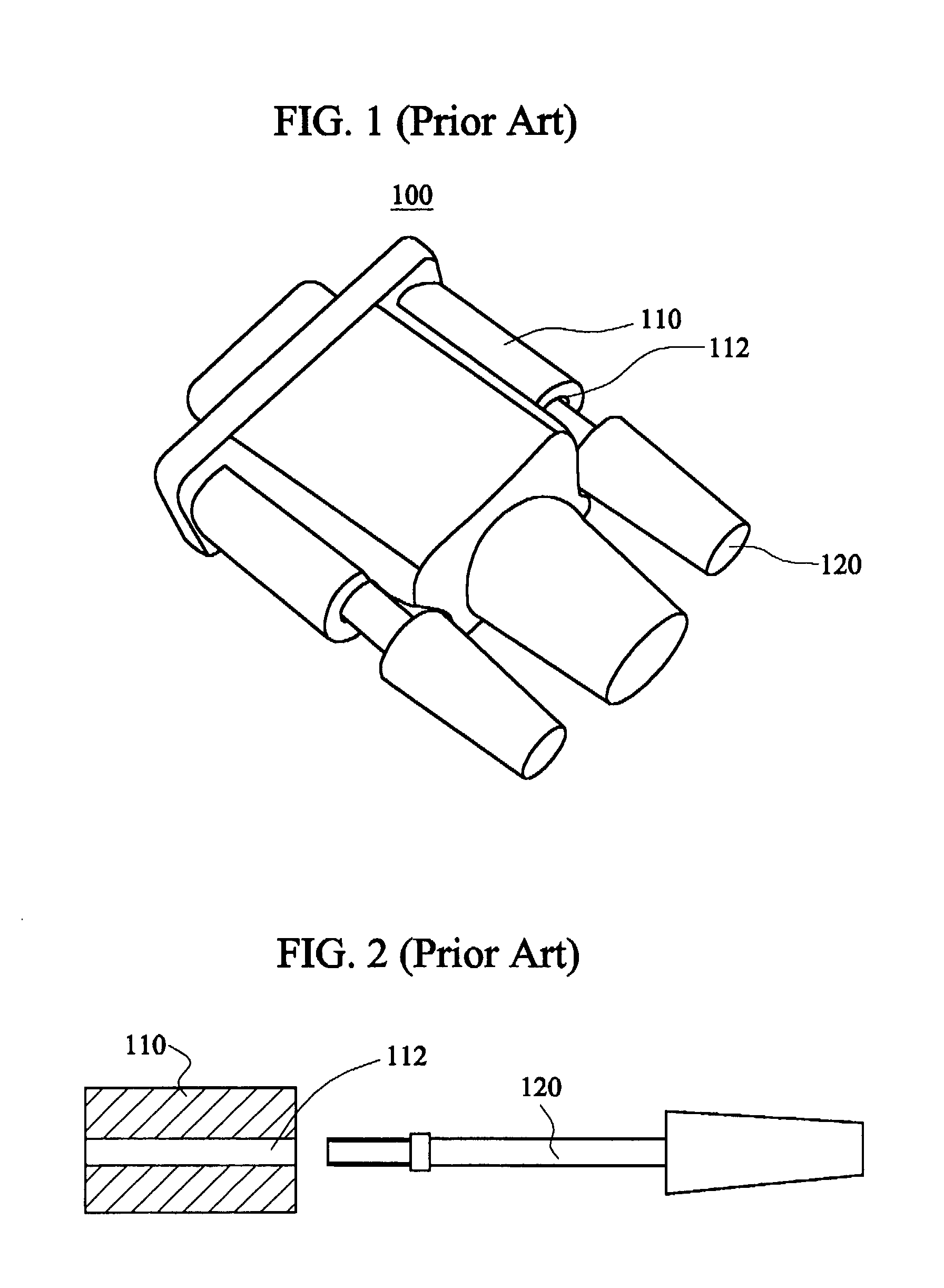
BACKGROUND OF THE INVENTION [0001] 1. Field of the Invention [0002] The invention relates to an electrical connector capable of interrupting an ESD (ElectroStatic Discharge) path, and more particularly to an electrical connector using an insulation medium to interrupt an ESD path. [0003] 2. Description of the Related Art [0004] Electrical connectors are widely used in computers and computer peripheral apparatuses such as scanners and printers. In order to prevent the signal transmitted through the electrical connector from being interfered by electrostatic charges on the human hands, the electrical connectors must have the capability of the ESD protection. [0005]FIG. 1 is a pictorial view showing a conventional electrical connector 100. FIG. 2 is a side view showing the connector of FIG. 1. Referring to FIGS. 1 and 2, the electrical connector 100 includes a body 110 and a bolt 120. The body 110 has a through hole 112 and the bolt 120 passes through the through hole 112. When the ele...

Claims


Application Information

Patent Timeline
IPC IPC(8): H01R3/00
CPCH01R13/621H01R13/6485
Inventor LIN, CHIN-YUANLIN, YI-KAILIN, SHENG-LEE
Owner AVISION
Learn More