System for inspecting a repair or joint consisting of a composite material applied to a structure

a composite material and repair technology, applied in the field of composite material inspection systems, can solve the problems of composite material failure, composite material failure, and higher probability of defects, and achieve the effect of low cost and very effectiv

Pending Publication Date: 2021-08-19
PETROLEO BRASILEIRO SA (PETROBRAS) +1
View PDF13 Cites 0 Cited by
  • Summary
  • Abstract
  • Description
  • Claims
  • Application Information

AI Technical Summary

Benefits of technology

[0015]The main objective of this invention is to provide a low-cost, very effective system to inspect a repair or joint made of composite material applied to a structure.

Problems solved by technology

In the oil, gas, and energy industries, the history of failures with composite materials is predominantly related to defects in assembly or problems during application of coatings in the field.
In both cases, the application conditions are usually unfavorable, resulting in a higher probability that defects will occur, such as: adhesion failures (on metal-composite interface and composite-composite interfaces); delamination (adhesion failures between the layers of the composite); inclusions (presence of bubbles and foreign objects between the composite layers), and non-uniform distribution of fibers in the composite.
There may also be defects in the structure arising from the component manufacturing process.
Defects in protective coatings and repairs may compromise the efficacy of the protection or structural reinforcement.
If not detected and corrected, defects in joints and connections of composite pipe structures may progress and lead to operational failures, producing the risk of product leakage.
Repairing metal pipes using composite materials has grown in the field; however the lack of effective field inspection techniques greatly restricts their use.
However, detecting internal defects using shearography or thermography requires the generation of a thermal gradient (excitation) inside the composite.
However, continuous (online) monitoring techniques are very expensive, as they require a system dedicated entirely to monitoring.

Method used


Image

  • System for inspecting a repair or joint consisting of a composite material applied to a structure
  • System for inspecting a repair or joint consisting of a composite material applied to a structure
  • System for inspecting a repair or joint consisting of a composite material applied to a structure

Examples


Embodiment Construction

[0023]First, please note that the following description will begin with the preferred realization of the invention. As will be evident to anyone skilled in the matter, however, the invention is not limited to this particular realization.

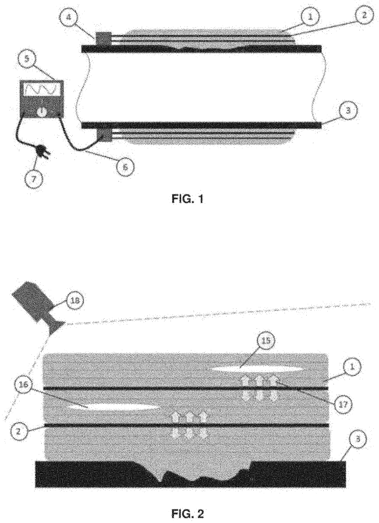
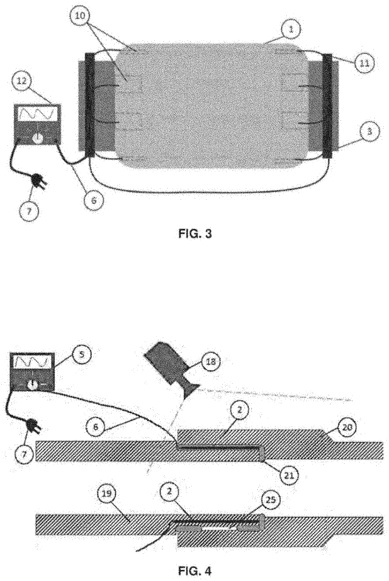
[0024]The system for inspecting a repair or joint made of composite material applied to a structure, according to this invention, comprises at least one exciter or element that is excitable to a thermal and / or vibrational stimulus, in which the at least one exciter or excitable element is integrated in the repair or joint.

[0025]FIG. 1 shows a cross schematic view of a first realization of the system of this invention in a composite repair 1 in a pipe 3. In this first realization, applied to a composite repair 1, the excitable element is at least one layer of a material that is excitable to a thermal and / or vibrational stimulus. More preferably, this layer that is excitable to a thermal and / or vibrational stimulus is a carbon fiber layer 2.

[0026]Depen...


PUM

PropertyMeasurementUnit
vibrational stimulusaaaaaaaaaa
frequencyaaaaaaaaaa
thermalaaaaaaaaaa

Abstract

This invention relates to inspection techniques for use on composite joints and repairs. In this context, this invention proposes a system for inspecting a repair or joint consisting of a composite material applied to a structure, comprising at least one exciter or element that is excitable (2, 10) to a thermal and/or vibrational stimulus, the at least one exciter or excitable element (2, 10) being integrated into the repair (1) or joint.

Description

FIELD OF THE INVENTION[0001]This invention relates to techniques for inspecting materials. More specifically, this invention is in relation to techniques for inspecting composite joints and repairs.BACKGROUND OF THE INVENTION[0002]Composite materials are increasingly being used in various industrial segments. The aerospace sector is the area that uses this type of material the most. However, the oil, gas and energy industries are following this trend, mainly as a function of the high resistance / weight relationship, immunity to corrosion, and the possibility of “cold” application of these materials. In the oil and gas industry, the possibility of cold application of joints and repairs is quite attractive, as it eliminates the need to isolate the environment and ensure it is free of the risks of combustion and explosion.[0003]Two types of uses for composite materials are being established in the oil, gas, and energy industries: repairs using composite materials, and structural element...

Claims


Application Information

Patent Timeline
Patent Type & Authority Applications(United States)
IPC IPC(8): G01N29/04G01N25/72G01N29/24G01N29/34B29C65/82B29C65/00
CPCG01N29/04G01N25/72G01N29/2437G01N29/348B29C65/8261B29K2309/08B29C66/1282B29C66/7212G01N2291/0289G01N2291/0231B29C65/8292B29C66/5221B29C66/12841B29C65/8253B29C65/48B29C66/342B29C66/721G01N29/045G01N29/043B29C73/04B29K2307/04
Inventor ANTONIO KAPP, WALTERAZEVEDO PERRUT, VALBERDAMASCENO SOARES, SERGIOEDUARDO BENEDET, MAUROUBIRAJARA NOGUEIRA, JAMESEMMENDOERFER, GUSTAVOAPARECIDO ALVES DA SILVA, FABIOPEDRO WILLEMANN, DANIELALBERTAZZI GONCALVES JUNIOR, ARMANDOVIEIRA FANTIN, ANALUCIAFAMPA SEABRA D ALMEIDA, ANA LUCIA
Owner PETROLEO BRASILEIRO SA (PETROBRAS)
Why Eureka
Try Eureka