
Method of Altering A Fluid-Borne Contaminant

a technology of fluid-borne contaminants and fluid-borne contaminants, which is applied in the direction of lighting and heating apparatus, heating types, separation processes, etc., can solve the problems of physical destruction of infrastructure and the use of these buildings, and achieve the effect of low cost and effective

Active Publication Date: 2011-03-17
THE RES FOUND OF STATE UNIV OF NEW YORK
View PDF3 Cites 0 Cited by
  • Summary
  • Abstract
  • Description
  • Claims
  • Application Information

AI Technical Summary

Benefits of technology

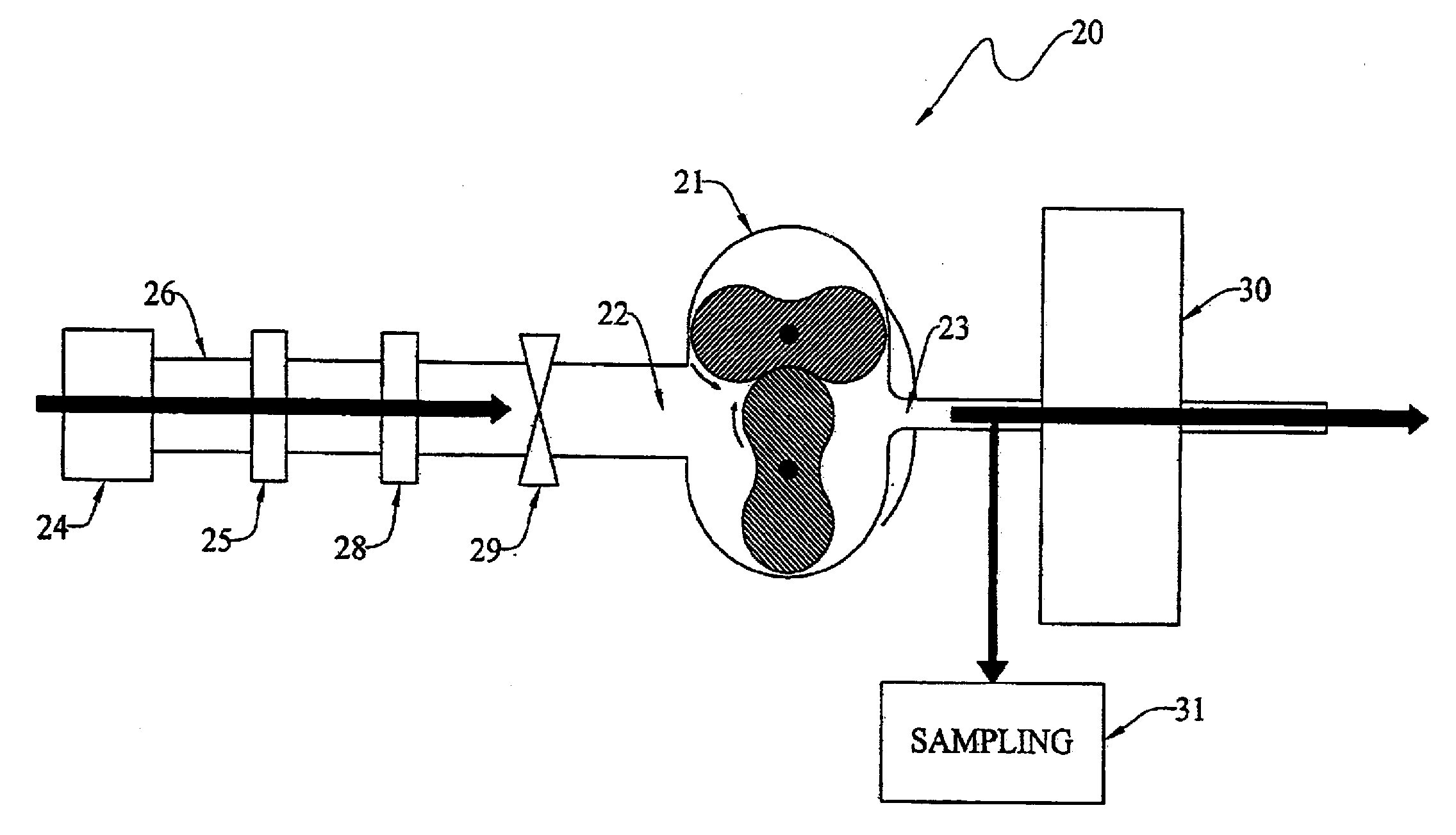
[0008]The improved method broadly includes the steps of: providing a pump (21) having an inlet (22) and an outlet (23); connecting the pump inlet to a source (24) of contaminated fluid; operating the pump at a pressure ratio of at least 2.0 so as to sufficiently elevate the temperature of the fluid and contaminants passing through the pump; and controlling the time during which the temperature of the fluid and contaminants are so elevated; thereby to purify the fluid passing through the pump.
[0012]The time of passage may be controlled by restricting the flow of fluid and contaminants passing through the pump, and / or any associated upstream or downstream elevated temperature portion.
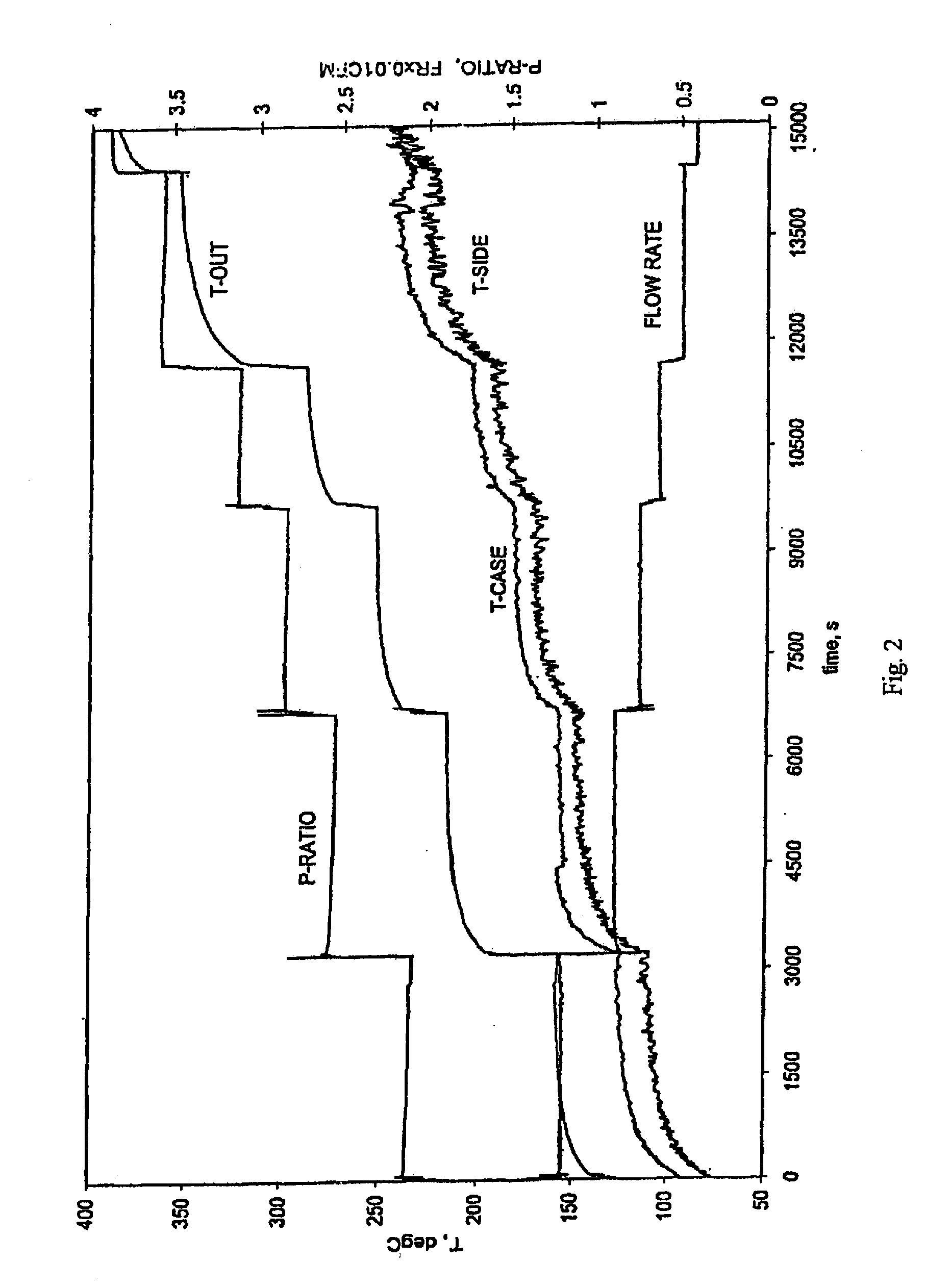
[0019]In another aspect, the invention provides an improved method of purifying a fluid having fluid-borne contaminants, which method includes the steps of: providing a pump having an inlet and an outlet; connecting the pump inlet to a source of contaminated fluid; operating the pump so as to elevate the temperature of the fluid and contaminants passing through pump to at least about 200° C.; and controlling the time during which the temperature of the fluid and contaminants are elevated; thereby to purify the fluid passing through the pump.
[0022]Still another object is to provide an effective and low-cost method of purifying a contaminated fluid.

Problems solved by technology

Some of these attacks are physically destructive of the infrastructure, whereas others are intended to deny the use of a facility.
This denied the government the use of these buildings during a period of remediation and cleaning.

Method used


Image

  • Method of Altering A Fluid-Borne Contaminant
  • Method of Altering A Fluid-Borne Contaminant
  • Method of Altering A Fluid-Borne Contaminant

Examples


Embodiment Construction

[0032]At the outset, it should be clearly understood that like reference numerals are intended to identify the same structural elements, portions or surfaces consistently throughout the several drawing figures, as such elements, portions or surfaces may be further described or explained by the entire written specification, of which this detailed description is an integral part. Unless otherwise indicated, the drawings are intended to be read (e.g., cross-hatching, arrangement of parts, proportion, degree, etc.) together with the specification, and are to be considered a portion of the entire written description of this invention. As used in the following description, the terms “horizontal”, “vertical”, “left”, “right”, “up” and “down”, as well as adjectival and adverbial derivatives thereof (e.g., “horizontally”, “rightwardly”, “upwardly”, etc.), simply refer to the orientation of the illustrated structure as the particular drawing figure faces the reader. Similarly, the terms “inwa...


PUM

PropertyMeasurementUnit
temperatureaaaaaaaaaa
pressure ratioaaaaaaaaaa
pressureaaaaaaaaaa

Abstract

An improved method of purifying a fluid having fluid-borne contaminants I including the steps of: providing a pump (21) having an inlet (22) and an outlet (23); connecting the pump inlet to a source (24) of contaminated fluid; operating the pump at. a pressure ratio of at least 2.0 so as to sufficiently elevate the temperature of the fluid and contaminants passing through the pump, or, alternatively, operating the pump so that the outlet temperature of the fluid and contaminants passing therethrough is at least about 200° C.; and controlling the time during which the temperature of the fluid and contaminants are elevated; thereby to alter or convert substantially all of the contaminants passing through the pump.

Description

CROSS-REFERENCE TO RELATED APPLICATIONS[0001]This application is a Continuation-in-Part and claims the benefit of U.S. application Ser. No. 12 / 035,418 filed Feb. 21, 2008, which is a Continuation of U.S. application Ser. No. 10 / 765,807 filed Jan. 27, 2004, now U.S. Pat. No. 7,335,333 issued Feb. 26, 2008, which in turn claims the benefit of U.S. Provisional Application No. 60 / 445,979 filed Feb. 7, 2003 and Provisional Application No. 60 / 486,507 filed Jul. 11, 2003, the disclosures of which are hereby incorporated by reference.TECHNICAL FIELD[0002]The present invention broadly provides an improved method of altering a fluid-borne contaminant, and, more particularly, to an improved method for efficiently altering or converting a particulate, chemical or biological contaminant in a compressible gas stream to a less-objectionable form.BACKGROUND ART[0003]The events of Sep. 11, 2001 have demonstrated that we live in a new era. Terrorists have demonstrated a willingness and ability to att...

Claims


Application Information

Patent Timeline
Patent Type & Authority Applications(United States)
IPC IPC(8): B01D46/00F24F8/00
CPCA61L9/00Y02B30/78B01D53/34B01D53/8671B01D2257/91B01D2257/93B01D2259/4508F04C18/126F04C2270/19F04C2270/44F24F3/16F24F11/0017F24F2003/1628F24F2003/1642B01D53/005F24F11/30F24F2110/50F24F8/96F24F8/167Y02B30/70F24F8/00
Inventor GARVEY, JAMES F.LORDI, JOHN A.MOLLENDORF, JOSEPHFELSKE, JAMES D.
Owner THE RES FOUND OF STATE UNIV OF NEW YORK
Learn More