
Tool carrying case for cordless power saws and drills

a cordless power saw and tool carrying case technology, applied in the field of storage cases, can solve problems such as cumbersome exercise, and achieve the effects of facilitating storage and carriage of cordless power saws, enhancing assembly procedures, and adding rigidity or structural integrity

Inactive Publication Date: 2006-10-05
TRAVEL CADDY
View PDF79 Cites 13 Cited by
  • Summary
  • Abstract
  • Description
  • Claims
  • Application Information

AI Technical Summary

Benefits of technology

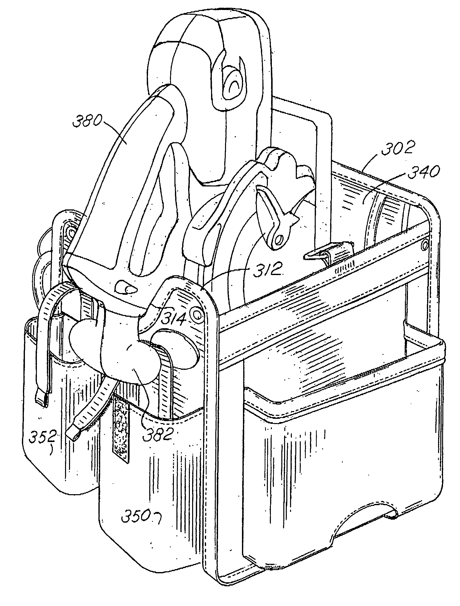
[0006] Briefly, embodiments of the present invention comprise a storage case which includes generally congruently shaped, relatively rigid or semi-rigid, spaced and opposed end panels connected by a relatively rigid bottom panel. Flexible fabric, spaced opposite side panels extend between the opposite side edges of the end panels. The rigid or semi-rigid end and bottom panels are typically covered on both sides with a fabric or flexible material, and in one embodiment a single continuous binding is stitched to join substantially all of the fabric material covering the end and bottom panels thereby enhancing the assembly procedure for the storage case and providing a desirable visual impression. The end panels may each have a generally rectangular shape with one end panel notched to facilitate storage and carriage of a cordless power saw. The flexible or partially reinforced side panels optionally include a rigid stiffening bar or rod member sewn or captured in a passage extending between the end panels to thereby provide additional rigidity or structural integrity to the carrying case. The side panels may be trapezoidally configured. A protective flap may be included on the inside of the tote or case to retain and protect rotary saw blades, for example. A metal or plastic loop may be incorporated or attached to the inside of a sidewall for receipt of a cordless drill.
[0010] A further object of the invention is to provide a storage case which has an aesthetically pleasing appearance to thereby enhance the marketability of the carrying case.
[0011] Yet another object of the invention is to provide a carrying case for tools and the like which is economical, easy to manufacture, constructed of rugged materials and which is highly utilitarian.

Problems solved by technology

Carrying such tools along with extra batteries, saw blades and other accessories is often a challenge and may be a cumbersome exercise.

Method used


Image

  • Tool carrying case for cordless power saws and drills
  • Tool carrying case for cordless power saws and drills
  • Tool carrying case for cordless power saws and drills

Examples


Embodiment Construction

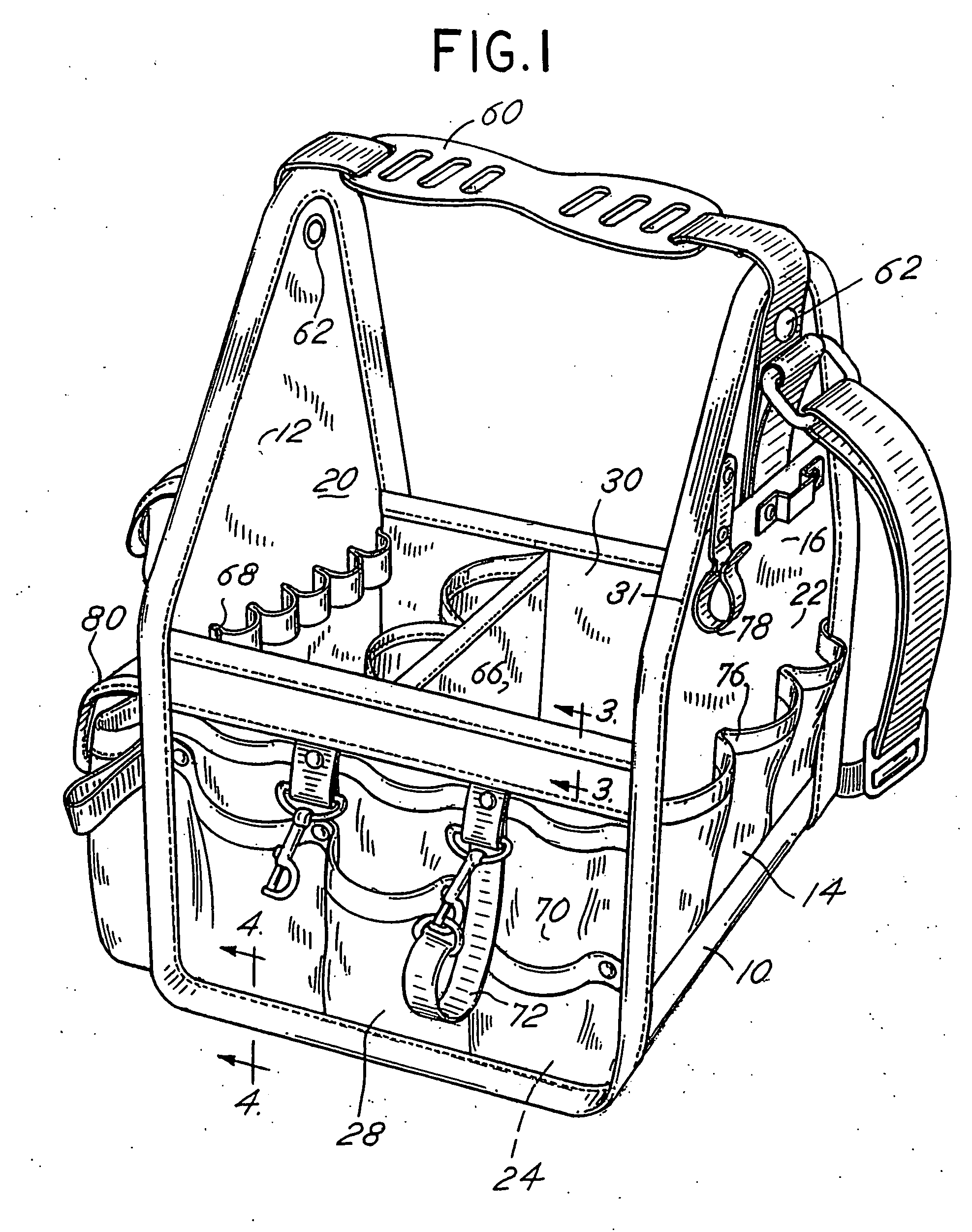
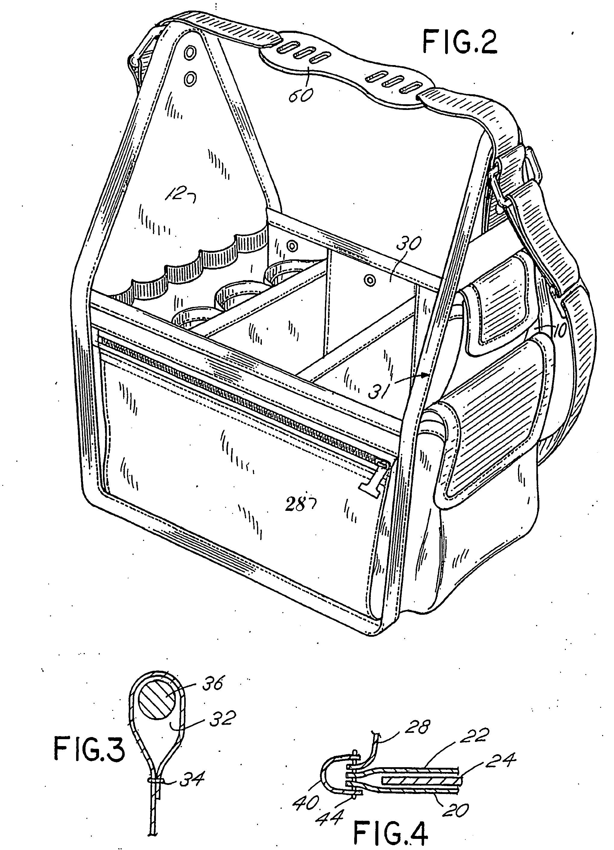
[0029] The tool storage and carrying case of the invention is depicted in first and second embodiments in FIGS. 1 and 2, respectively, and a third embodiment in FIG. 5. The first embodiment of FIG. 1 is physically smaller than the second embodiment of FIG. 2. The methodology of assembly of the cases of FIGS. 1, 2 and 5 is substantially the same and the configuration of the various carrying cases is substantially the same. Another embodiment is depicted in FIG. 5. Additional embodiments are depicted in FIGS. 6-14.

[0030] Referring therefore to FIG. 1, as well as FIGS. 3 and 5, the carrying case of the invention includes a first end panel 10 and a second, spaced end panel 12. The panels 10 and 12 are congruent or, in other words, substantially identical in size, shape and configuration. The first and second panels 10 and 12 include a lower generally rectangular section 14 and an upper triangular or trapezoidal section 16. The triangular section 16 has a generally isosceles triangular ...


PUM


Abstract

A storage and carrying case includes spaced end panels and a bottom panel all joined together by means of a fabric over layer and a fabric under layer which are stitched together by a binding which also connects to side panels to form an enclosure for tools or the like. A single binding may thus be utilized to join all of the flexible fabric materials which retain the semi-rigid or rigid panels forming the enclosure. The case further includes panels constructed to facilitate storage and carrying of cordless power tools.

Description

CROSS REFERENCE TO RELATED APPLICATIONS [0001] This is a continuation in part application of continuation application Ser. No. 11 / 340,261, filed Jan. 26, 2006, which is a continuation application of Ser. No. 10 / 982,319, filed Nov. 11, 2004, now U.S. Pat. No. 6,991,104, and Ser. No. 10 / 393,125, filed Mar. 20, 2003, now U.S. Pat. No. 6,823,992, which is based on provisional application Ser. No. 60 / 365,966 filed Mar. 20, 2002, all of which are entitled “Tool Carrying and Storage Case” and for all of which priority is claimed and all of which are incorporated herein by reference. BACKGROUND OF THE INVENTION [0002] In a principal aspect, the present invention relates to a storage case for carrying tools and other items. [0003] Gardeners, tradesmen, workmen and the like often carry and transport their tools and / or equipment in an open top carrying case. An open top carrying case enables quick access to the contents of the case. Such a case also facilitates carrying of multiple tools and i...

Claims


Application Information

Patent Timeline
Patent Type & Authority Applications(United States)
IPC IPC(8): B65D85/28A45C11/26
CPCA45C5/06A45C13/02A45C13/04B25H3/02A45C2005/035A45F3/02A45C2005/032
Inventor REDZISZ, ANDREZJGODSHAW, DONALD E.
Owner TRAVEL CADDY
Learn More