[0008] Due to the free end portion, attachment of the spring onto elongate members, e.g. for fastening of the end windings in grooves has been facilitated, and in particular in combination with manufacturing of valves, e.g. valves of a very compact design, attachment of the spring to the valve member has been facilitated. In the
assembly procedure, an assembly tool, e.g. a
piston or stamp can punch the spring in an axial direction down over an end portion of the elongate member by exerting pressure on the outwardly extending free wire end. To further facilitate this pressing process, a part of the connecting wire portion may also extend outwardly to form a protrusion by which a pressing tool can press the spring axially onto the elongate member.
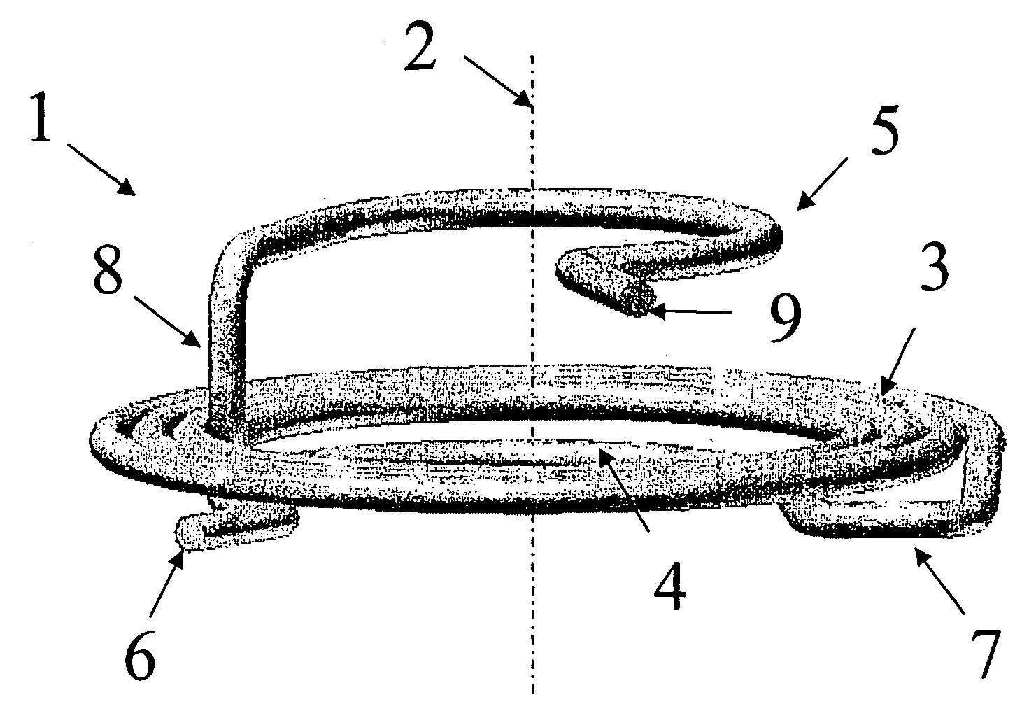
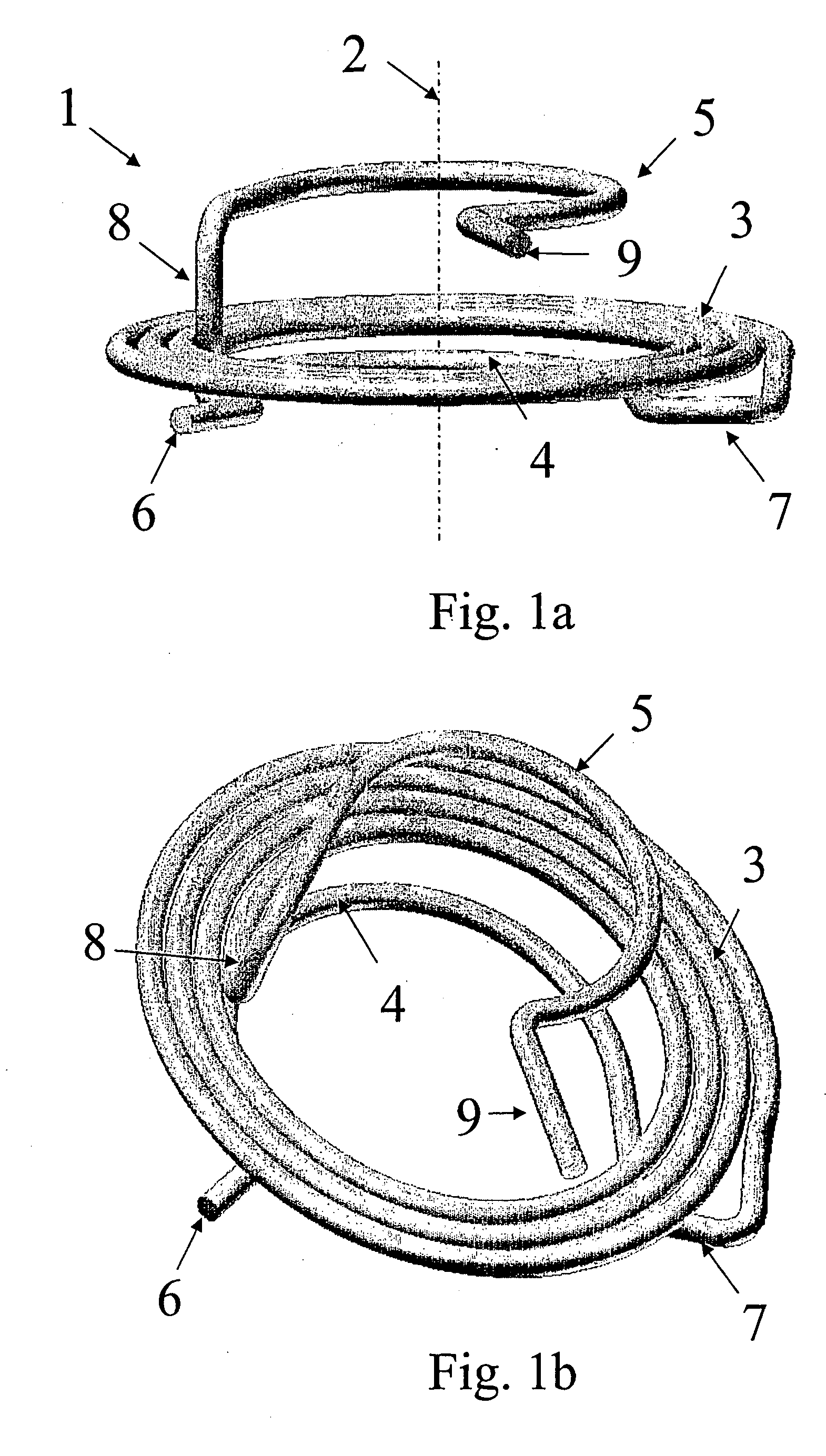
[0012] To further facilitate the fitting of the end winding of the spring into a groove, the end winding could be disposed at a larger distance from an adjacent winding than the distance between windings of the intermediate portion. As an example, the connecting portion of one of the end windings could extend in the axial direction thereby to displace the end winding a certain distance away from the intermediate portion. In another example, the
pitch, i.e. the degree of slope of the
helical windings, could be increased towards the end windings. Due to the larger distance, it is easier to isolate that end winding from other windings for easy locating of the winding into the groove. In one embodiment, both of the end windings comprises an arcuate portion wherein the wire extends around the longitudinal axis, a connecting wire portion extending towards the intermediate portion, and a free wire end portion extending away from the longitudinal axis, e.g. radially away from the axis. In this embodiment, the connecting wire portion of the first end winding could extend outwardly away from the longitudinal axis to form a protrusion on which the previously mentioned assembly tool can press the spring in an axial direction onto an elongate member. The connecting wire portion of the second end winding could extend in the longitudinal direction, i.e. parallel to the longitudinal axis, to provide the distance between the end winding and the adjacent winding of the intermediate portion.
[0013] To further improve the assembly procedure, the end winding could be wound in a direction which is opposite the general coiling direction of the windings of the intermediate portion. By such reversing of the winding direction with respect to the end winding, a better defined opening could be created for the valve member or
plunger to move radially into a space encircled by the end winding. In particular, the combination between the joining of the end winding to the intermediate portion by a wire portion extending in the axial direction and the reversing of the direction of the end winding with respect to the intermediate portion, could create a free
wire loop with a well defined radial opening into the inner space for easy
insertion of a plunger or valve member into that space, and for fixation of the
wire loop into a groove of the plunger or valve member.
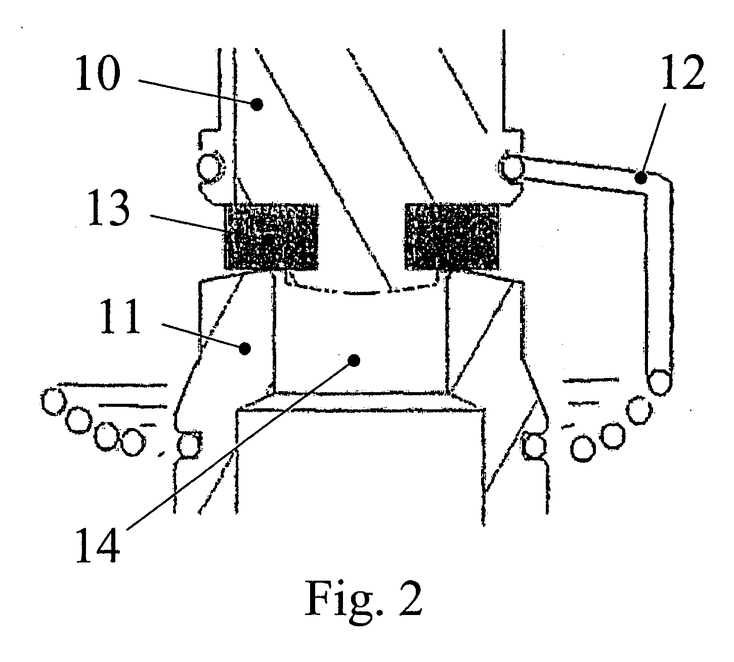
[0015] In the foregoing description, the spring is disclosed in connection with a valve assembly. The valve could be a regular valve with a main valve passage and a valve member operable to control the flow through the passage. In one embodiment, however, the valve is a
servo valve with a
pilot closure member which is opened by the plunger under influence of
magnetism, i.e. a solenoid operated valve. In this design, the passage in question could be a
pilot passage between a main valve passage and a
pilot chamber, and the spring could be applied to join the plunger and the
pilot valve member. To facilitate the attachment of the spring onto the plunger and / or onto the valve member, at least one of the plunger and the valve member may have an axial end portion tapering conically inwardly from the groove towards the end thereby forming an end with a smaller radial size than the radial size of the groove. This will allow the end of the valve member or plunger to be inserted into the spring in an easy manner and by further pressing of the valve member or plunger into the spring, and optionally with simultaneous manipulation of the gripping means, the end winding of the spring is easily entered into the groove, e.g. by use of a pressing tool of the aforementioned kind. Analogously, the spring may in general be applied for attachment to any component of a valve, and it may thus substitute e.g. the springs disclosed in applicant's previous application, c.f. US 2003 / 0132409.

