Non-contact porous air bearing and glass flattening device

a technology of porous air bearings and flattening devices, which is applied in the field of non-contact porous air bearings, can solve the problems of flatness errors, glass edges may curl down, etc., and achieve the effects of reducing the cost and many of the problems associated with substrate sized vacuum chucks, reducing the number of natural thickness errors in glass or substrates, and reducing the cost of processing

Inactive Publication Date: 2006-10-05
NEW WAY MACHINE COMPONENTS
View PDF15 Cites 119 Cited by
  • Summary
  • Abstract
  • Description
  • Claims
  • Application Information

AI Technical Summary

Benefits of technology

[0016] The present invention is also directed to a technique for flattening glass. The common technique for holding large thin glass work pieces is to suck them down to a vacuum chuck the same size as the glass. In that method there are two main sources of flatness errors; the flatness of the chucks supporting the glass including any contamination which may be between the glass and the chucks and the thickness of the glass itself. By conveying the glass on a of film of air and employing precision zones adjacent to precision processes the cost and many of the problems associated with substrate sized vacuum chucks can be eliminated. A further advantage, and the subject of this patent application, is to design the precision zone so as to present the flattest possible surface for high-resolution lithography and or other precision processes. By positioning the vacuum preloaded air bearing array on the same side as the processing, natural thickness errors in the glass or substrate can be removed or minimized for processing.

Problems solved by technology

Additionally as the leading edge of the glass transits over the pressure nozzles there is a perturbation and the edge of the glass may curl down between the pressure nozzles.
In that method there are two main sources of flatness errors; the flatness of the chucks supporting the glass including any contamination which may be between the glass and the chucks and the thickness of the glass itself.

Method used


Image

  • Non-contact porous air bearing and glass flattening device
  • Non-contact porous air bearing and glass flattening device
  • Non-contact porous air bearing and glass flattening device

Examples


Embodiment Construction

[0028] Various preferred embodiments of the invention will be set forth in detail with reference to the drawings, in which like reference numerals refer to like elements throughout.

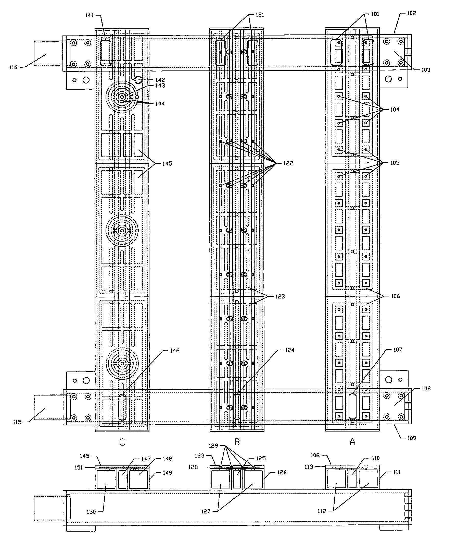
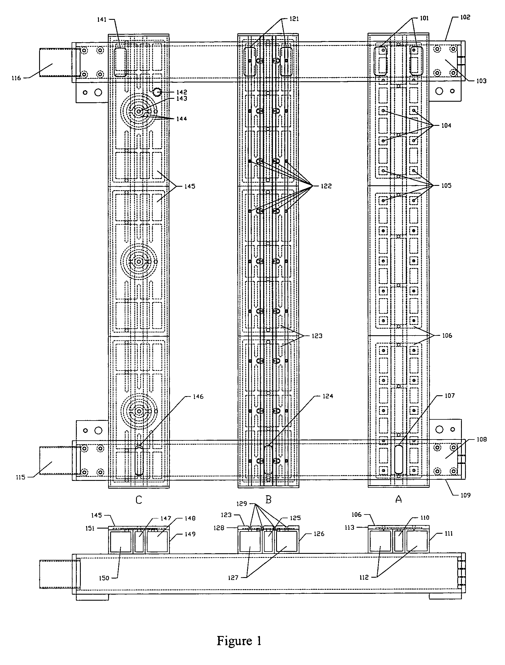
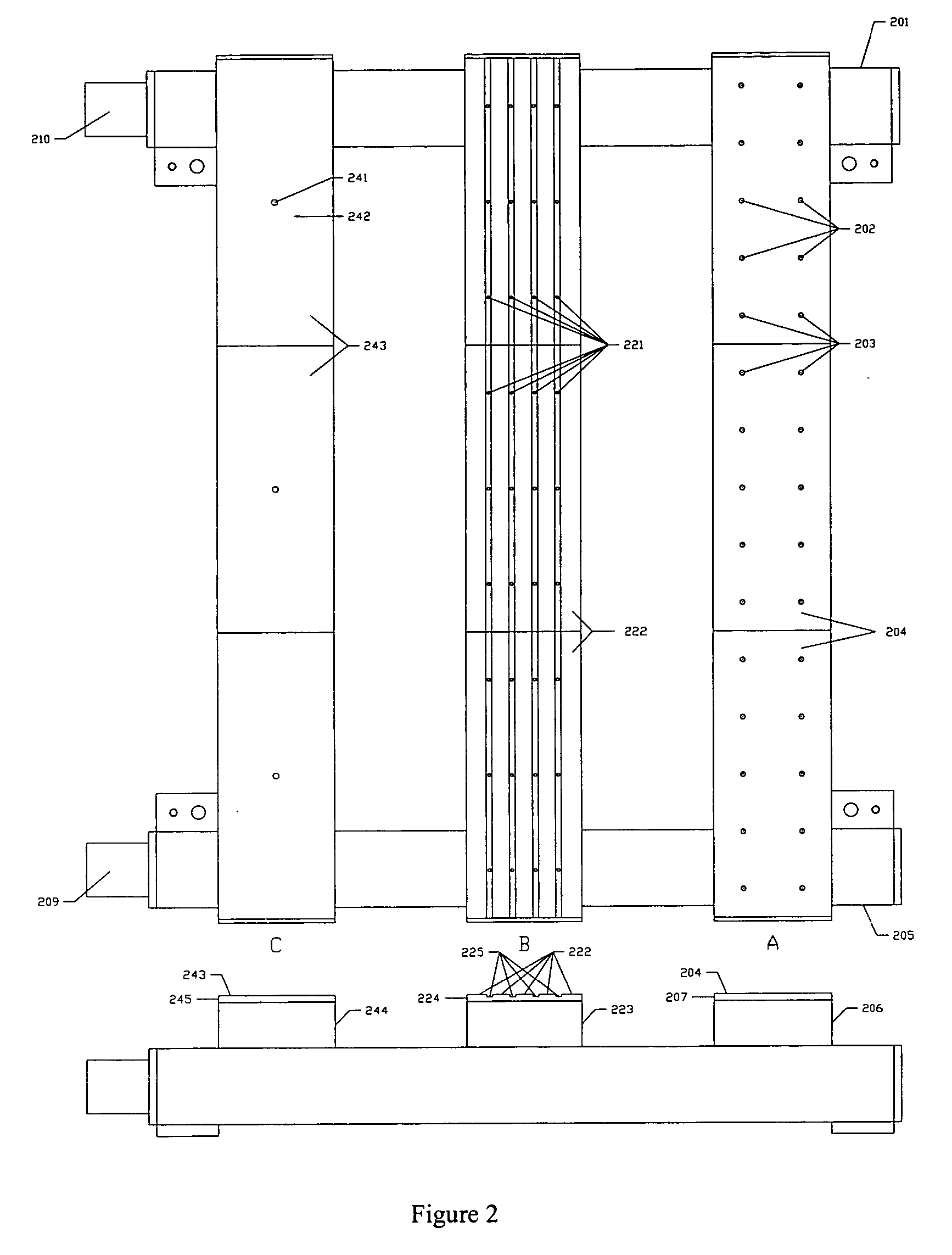
[0029] A device is disclosed for supporting and transporting thin substrates by levitating them on a porous media air bearing creating a pressurized film of air and preloading them against the air film by negative pressure areas. The pressure can be distributed most uniformly across the pressure areas by defusing the pressure through a porous media. Since the entire top surface the conveyer or precision chuck has air pressure bleeding out the surface it is not dependant on flow though the gap to support an area of increased load. Another advantage of the porous media air bearing is that because the air escapes from the whole surface the velocity of the air is very low, eliminating vertical air streams. Vacuum regions can be holes or grooves connected via orifices to vacuum plenums within the conveyer or ...


PUM

PropertyMeasurementUnit
pressuresaaaaaaaaaa
thicknessaaaaaaaaaa
thicknessaaaaaaaaaa

Abstract

Thin substrates, such as flat glass panels, are levitated on a porous media air bearing creating a pressurized film of air and preloaded against the air film by negative pressure areas. The pressure can be distributed most uniformly across the pressure areas by defusing the pressure through a porous medium. Such a bearing can be used for glass flattening by holding the glass such that the unevenness is migrated to the side opposite the side to be worked on.

Description

REFERENCE TO RELATED APPLICATIONS [0001] The present application claims the benefit of U.S. Provisional Patent Application No. 60 / 625,583 (Conf. No. 8294), filed Nov. 8, 2004, and U.S. Provisional Patent Application No. 60 / 644,981 (Conf. No. 7250), filed Jan. 21, 2005, both of whose disclosures are hereby incorporated by reference in their entireties into to present disclosure.FIELD OF THE INVENTION [0002] The invention is directed to a system and method for supporting thin work pieces, particularly glass, for precision inspection, coating, patterning, and other processes without contacting the work piece. DESCRIPTION OF RELATED ART [0003] Flat-panel display (FPD) screens especially for computer and large screen televisions have pushed manufacturers to processing very large and thin glass substrates. As the substrates get larger they become more difficult to handle with robotic arms due to deflections of the glass from its own weight. A method for transporting glass on a cushion of ...

Claims


Application Information

Patent Timeline
Patent Type & Authority Applications(United States)
IPC IPC(8): B07B9/00
CPCB65G49/065B65G51/03B65G2249/02B65G2249/04F16C32/0618C03B23/0235H01L21/67784F16C29/025C03B23/008
Inventor DEVITT, ANDREW J.
Owner NEW WAY MACHINE COMPONENTS
Why Eureka
Try Eureka