Electronic switch and operational method for transistor

a transistor and operation method technology, applied in the field of electronic switches, can solve problems such as inability to raise voltage, and achieve the effect of avoiding the body

Inactive Publication Date: 2006-10-05
NOVATEK MICROELECTRONICS CORP
View PDF19 Cites 46 Cited by
  • Summary
  • Abstract
  • Description
  • Claims
  • Application Information

AI Technical Summary

Benefits of technology

[0016] According to the present invention, the bulk of the transistor is dynamically switched to either the first terminal o...

Problems solved by technology

As a result, the v...

Method used


Image

  • Electronic switch and operational method for transistor
  • Electronic switch and operational method for transistor
  • Electronic switch and operational method for transistor

Examples


Embodiment Construction

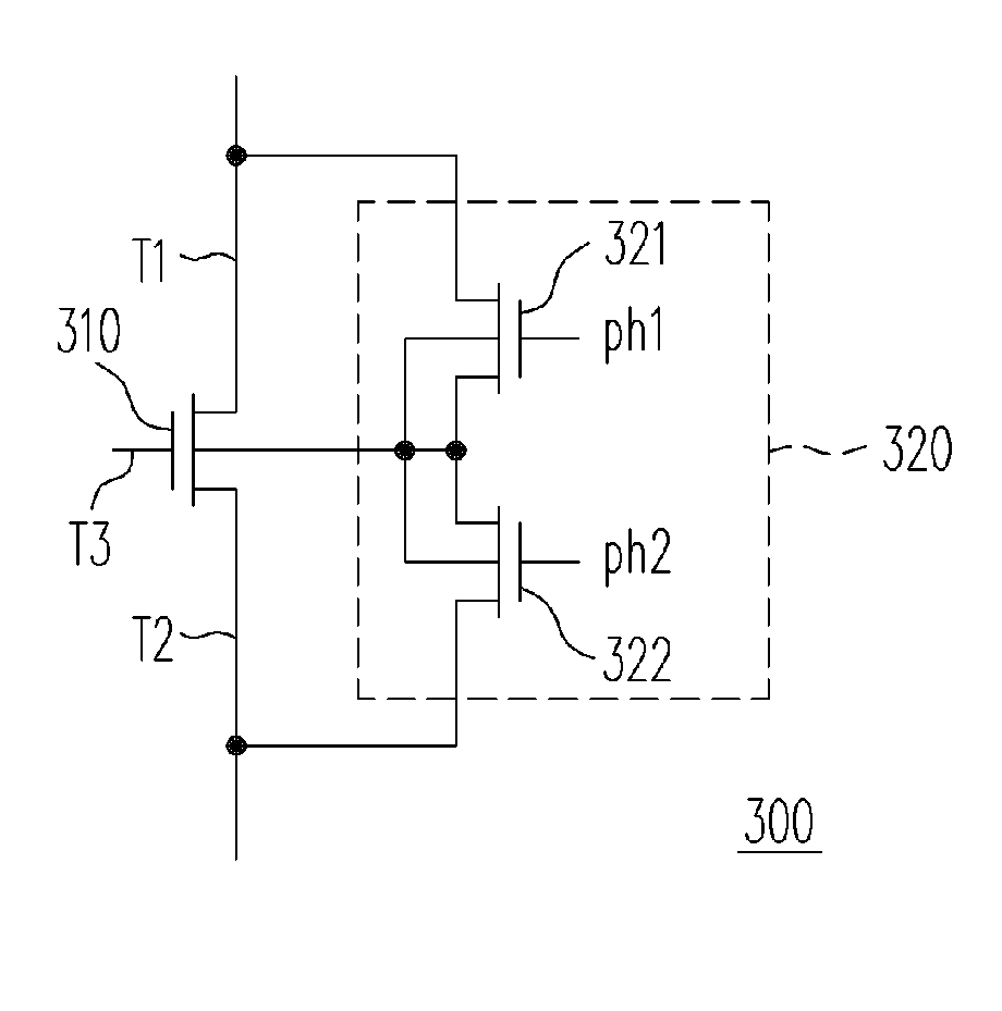
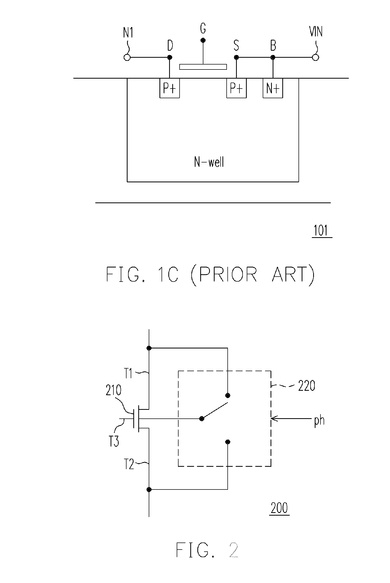
[0025]FIG. 2 is a schematic drawing showing an electronic switch according to an embodiment of the present invention. Referring to FIG. 2, the electronic switch 200 comprises the switch transistor 210 and the bulk switch 220. The switch transistor 210 at least comprises a first terminal T1, a second terminal T2 and a third terminal T3. The switch transistor 210 determines a connection status between the first terminal T1 and the second terminal T2 according to the third terminal T3. The bulk switch 220 is coupled to the bulk of the switch transistor 210. The bulk switch 220 determines whether to connect the bulk of the switch transistor 210 to the first terminal T1 of the switch transistor 210 or the second terminal T2 of the switch transistor 210 according to at least one control signal ph. In this embodiment, the switch transistor 210 is an NMOS transistor. When operating the electronic switch 200, the bulk of the switch transistor 210 is coupled to one of the first terminal T1 an...


PUM


Abstract

An electronic switch and an operational method for transistor are provided. The electronic switch includes a switch transistor and a bulk switch. The switch transistor has at least a first terminal, a second terminal and a third terminal. According to the third terminal, the connecting status between the first and the second terminal is determined. The bulk switch is coupled to the bulk of the switch transistor for determining whether to connect the bulk to the first or the second terminal of the switch transistor according to at least one control signal.

Description

CROSS-REFERENCE TO RELATED APPLICATION [0001] This application claims the priority benefit of Taiwan application serial no. 94109941, filed on Mar. 30, 2005. All disclosure of the Taiwan application is incorporated herein by reference. BACKGROUND OF THE INVENTION [0002] 1. Field of the Invention [0003] The present invention relates to an electronic switch, and more particularly to an electronic switch for preventing the incorrect turn-on of PN-junction forward bias, and an operational method for transistor. [0004] 2. Description of the Related Art [0005] Electronic circuits usually include many electronic switches. Most of the electronic switches are composed of MOS transistors. A connection between source and drain is determined by a control signal of gate. In such an electronic circuit, the bulk of the transistor is coupled to a fixed voltage. [0006] The following is to describe the incorrect turn-on issue of PN-junction forward bias in a charge pump circuit. FIG. 1A is a drawing ...

Claims


Application Information

Patent Timeline
IPC IPC(8): H03K3/01
CPCH03K17/063H03K2217/0018H03K17/102
Inventor YEN, CHIH-JEN
Owner NOVATEK MICROELECTRONICS CORP
Why Eureka
Try Eureka