
Displaying method and image display device

a display method and display method technology, applied in the field of display methods and image display devices, can solve the problems of reducing the quality of the display, reducing the image quality, and no further adjustment, and achieve the effect of uniform color distribution, equal or similar, and low color shi

Active Publication Date: 2006-10-05
INNOLUX CORP
View PDF7 Cites 60 Cited by
  • Summary
  • Abstract
  • Description
  • Claims
  • Application Information

AI Technical Summary

Benefits of technology

[0014] It is therefore an objective of the present invention to provide a displaying method and an image display, which divide a gray scale into two and utilize the concept of pixel sharing to achieve a low color shift (LCS) display mode, thereby preventing phenomena such as color shift and uneven brightness.
[0020] By utilizing a more advanced algorithm to process image signals, the present invention can provide an equivalent or even doubled image quality or resolution compared to the conventional process. Additionally, low color shift, uniform color distribution, and minimal black dots can be achieved under various viewing angles. Preferably, the displaying method of the present invention can be applied to both stripe type liquid crystal displays and staggered type liquid crystal displays. Consequently, the present invention can prevent color shift, and increase image brightness in the stripe type liquid crystal displays, and at the same time reduce the number of data drivers, preferably up to 33.33% in the staggered type liquid crystal displays. Moreover, the present invention can freely switch between the text mode and the LCS mode, and adjust the edge resolution of a displayed image, thereby producing a sharper picture.

Problems solved by technology

However, after the display is fabricated, no further adjustment can be made, and the fact that different regions correspond to different viewing angles specifically also reduces the quality of the display.
However, changes made within every two frames will result in flickering and only half of the pixels are actually involved in the displaying of an image at a particular viewing angle, thereby reducing the quality of the image and failing to solve the problems that occur in most observation circumstances.
Consequently, stripes caused by uneven brightness will appear on the display image and result in unsatisfying visual effects.
Additionally, the fact that the subpixels are not effectively arranged also reduces the sampling and rebuild ability of the image signals.

Method used


Image

  • Displaying method and image display device
  • Displaying method and image display device
  • Displaying method and image display device

Examples


Embodiment Construction

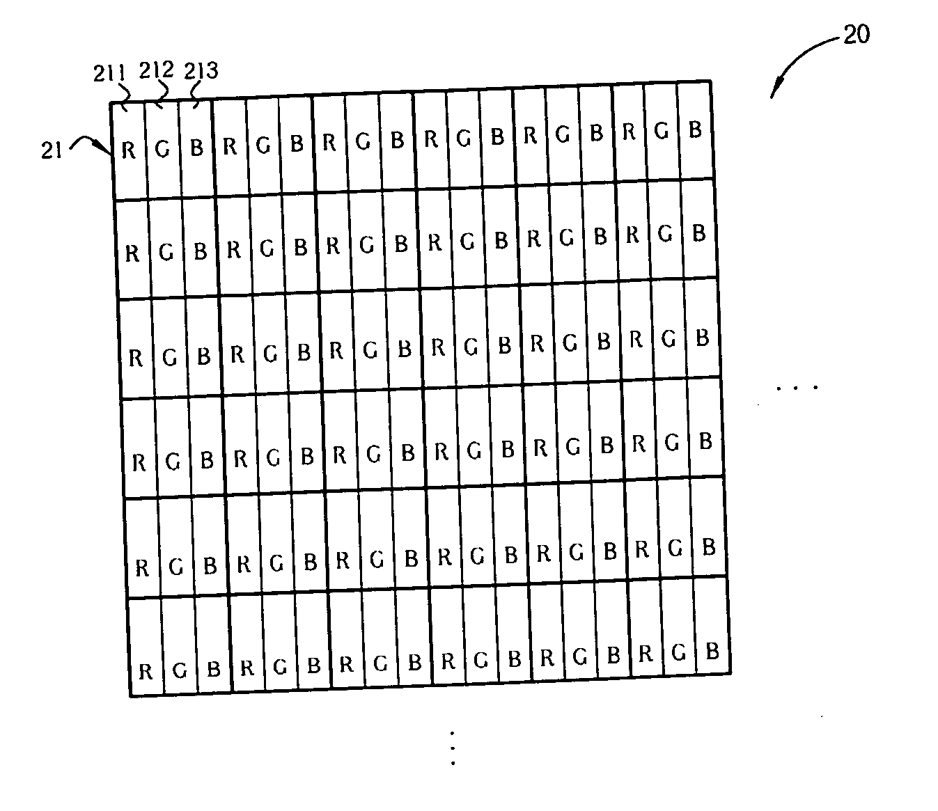
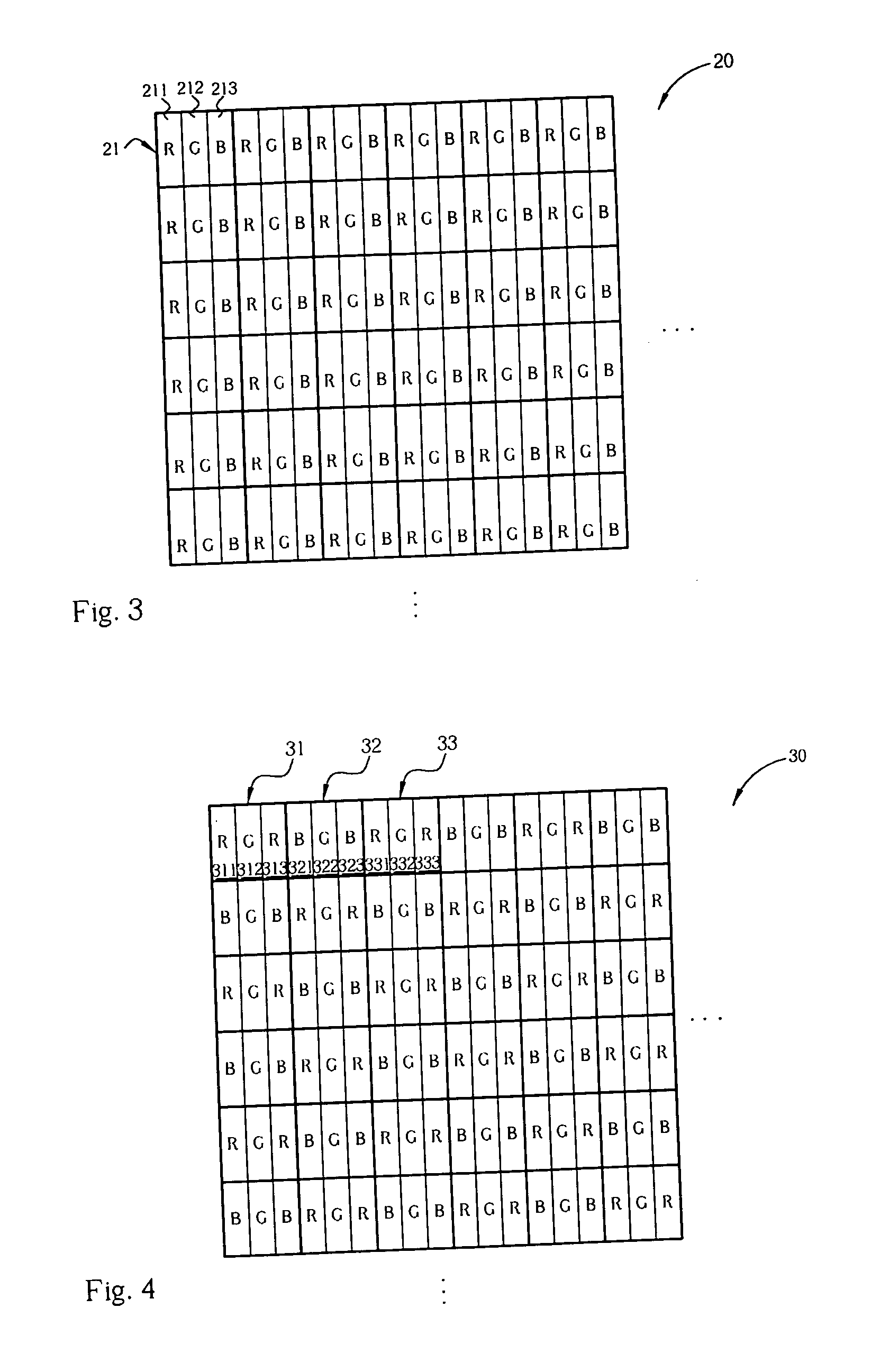
[0048] The displaying method of the disclosed embodiments of the present invention applies to an image display, such as a liquid crystal display, in which the liquid crystal display includes a plurality of pixels arranged in a matrix form, and each of the pixels includes at least one color subpixel. Generally, there primary colors of red, blue and green are used, but the invention is not limited thereto. FIG. 3 and FIG. 4 are diagrams showing the pixel arrangement of liquid crystal displays 20 and 30, respectively.

[0049] As shown in FIG. 3, the pixels of the liquid crystal display 20 are arranged in a stripe form, in which each pixel, such as the pixel 21, includes, e.g., three subpixels arranged in the order of a red subpixel 211, a green subpixel 212, and a blue subpixel 213. As shown in the figure, R indicates red subpixel, G indicates green subpixel, and B indicates blue subpixel. The liquid crystal display 20 is a stripe form liquid crystal display because the red subpixels, b...


PUM


Abstract

In a displaying method for use in an image display, an original gray scale is divided into a higher gray scale and a lower gray scale. Further, the color subpixels are divided into two groups corresponding to the higher and lower gray scales, respectively. The gray scale to be expressed by each subpixel is calibrated by weighing the original higher or lower gray scale for the pixel and the adjacent pixels and summing up the results. The color shift problem due to different visual angles can therefore be solved.

Description

[0001] This application claims the benefit of Taiwan application Serial No. 94110114, filed Mar. 30, 2005, the entirety of which is incorporated herein by reference. BACKGROUND OF THE INVENTION [0002] 1. Field of the Invention [0003] The invention relates to a displaying method and an image display device, and more particularly, to a displaying method and image display device capable of improving the color shift phenomenon. [0004] 2. Description of the Prior Art [0005] As incident lights passing through a liquid crystal layer from different angles generate different retardations, the refractive index of the light transmission will change according to different observation angles and result in different transmittance and different brightness while viewing from different angles. Hence, the light transmittance of a liquid crystal display being viewed from the front is different from the light transmittance of the same liquid crystal display being viewed from a side. Therefore, the brig...

Claims


Application Information

Patent Timeline
Patent Type & Authority Applications(United States)
IPC IPC(8): G09G3/36
CPCG09G3/3611G09G2320/0242G09G2300/0452G09G5/06
Inventor SHIH, MING-CHIAHSU, YING-HAO
Owner INNOLUX CORP
Learn More