

Multi-carrier transmitter apparatus, multi-carrier receiver apparatus and multi-carrier communication method
a multi-carrier transmitter and receiver technology, applied in multi-carrier communication, multi-frequency code system, multiplex communication, etc., can solve the problem of deterioration of error correction rate characteristic without obtaining any effective effect, and achieve the effect of improving error correction rate characteristi
- Summary
- Abstract
- Description
- Claims
- Application Information
AI Technical Summary
Benefits of technology
Problems solved by technology
Method used
Image

Examples
embodiment 1
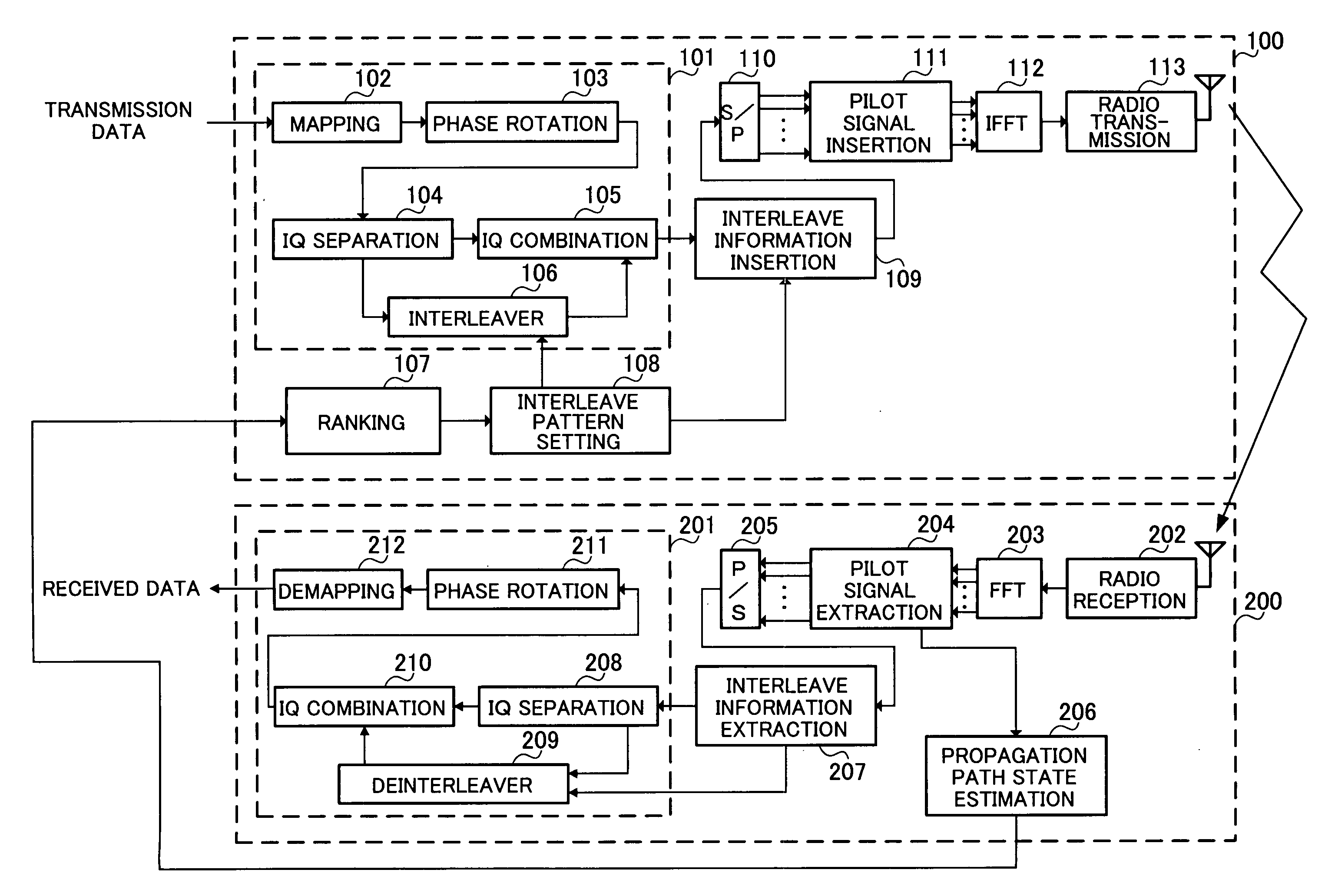
[0051]FIG. 3 shows the configuration of multicarrier transmission apparatus 100 and multicarrier reception apparatus 200 according to a multicarrier communication apparatus of the present invention. Multicarrier transmission apparatus 100 is provided on a first radio station and multicarrier reception apparatus 200 is provided on a second radio station that carries out radio communication with the first radio station.
[0052] In practice, the first radio station provided with multicarrier transmission apparatus 100 includes a reception section and the second radio station provided with multicarrier reception apparatus 200 includes a transmission section, but the reception section and transmission section of this embodiment are omitted in the explanations for simplicity.
[0053] Multicarrier transmission apparatus 100 includes modulation diversity modulation section 101 and inputs transmission data to mapping section 102 of modulation diversity modulation section 101. Mapping section 1...
embodiment 2
[0087]FIG. 9 in which parts corresponding to those in FIG. 3 are shown with the same reference numerals assigned shows the configurations of multicarrier transmission apparatus 300 and multicarrier reception apparatus 400 that receives and demodulates a signal from multicarrier transmission apparatus 300 according to Embodiment 2.
[0088] Multicarrier transmission apparatus 300 has a configuration similar to that of multicarrier transmission apparatus 100 according to Embodiment 1 except in that it has a different configuration of interleave pattern setting section 301 and includes interleave pattern table 302. Furthermore, multicarrier reception apparatus 400 has a configuration similar to that of multicarrier reception apparatus 200 according to Embodiment 1 except in that it includes interleave pattern table 401.
[0089] Here, interleave pattern table 302 of multicarrier transmission apparatus 300 stores a plurality of interleave patterns. Interleave pattern setting section 301 seq...
embodiment 3
[0101]FIG. 11 in which parts corresponding to those in FIG. 9 are shown with the same reference numerals assigned shows the configuration of multicarrier transmission apparatus 500 and multicarrier reception apparatus 400 that receives and demodulates a signal from multicarrier transmission apparatus 500 according to Embodiment 3.
[0102] Multicarrier transmission apparatus 500 has a configuration similar to that of multicarrier transmission apparatus 300 of Embodiment 2 except in that the configuration of interleave pattern setting section 501 is different. Furthermore, multicarrier reception apparatus 400 has a configuration similar to that of multicarrier reception apparatus 400 explained in Embodiment 2.
[0103] Interleave pattern setting section 501 is similar to interleave pattern setting section 301 in Embodiment 2 in that it sequentially reads a plurality of interleave patterns stored in interleave pattern table 302, performs a simulation using interleave patterns and channel ...
PUM
 Abstract
Description
Claims
Application Information