
Agricultural bagger with upper tunnel compaction

a technology of agricultural baggers and tunnels, applied in the field of agricultural baggers, can solve the problems of reducing so as to improve the flow of agricultural feed, reduce the risk of being sucked through and shredded by the primary compression mechanism, and increase the efficiency of agricultural baggers

Inactive Publication Date: 2006-10-12
WINGERT PAUL
View PDF9 Cites 0 Cited by
  • Summary
  • Abstract
  • Description
  • Claims
  • Application Information

AI Technical Summary

Benefits of technology

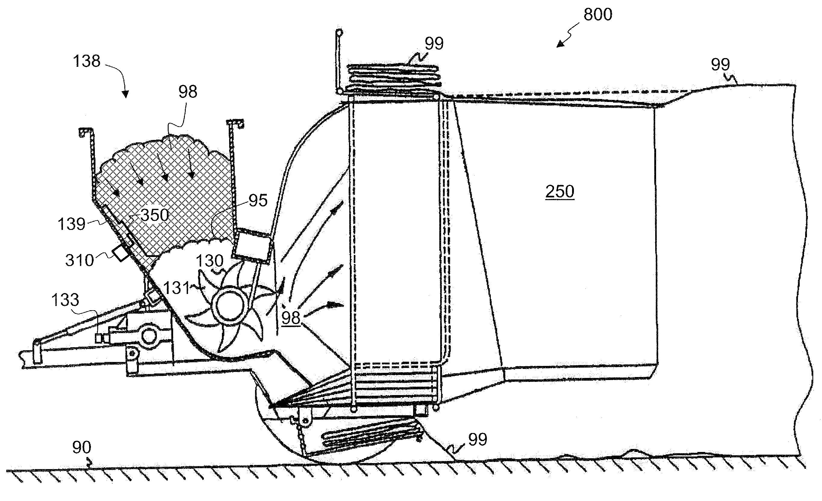
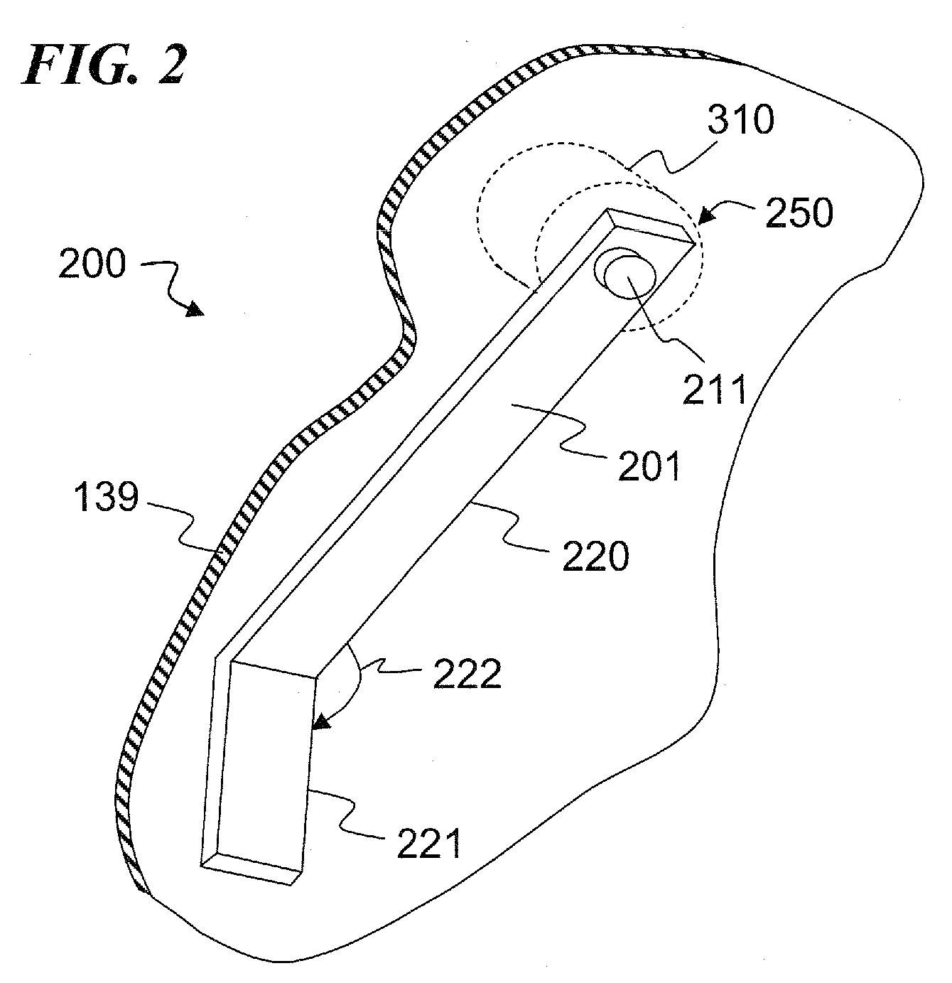
[0010] The invention provides an agricultural bagger apparatus for compacting feed into a horizontally deployed bag. The apparatus includes a primary compression mechanism and an input hopper that receives agricultural feed. The hopper has a sloping wall and a lower-end exit chute located to transfer the agricultural feed into the primary compression mechanism. The tapered hopper tends to cause the feed to bridge, stopping the feed from falling into the chute. The apparatus also includes a first motor coupled to the sloping wall of the input hopper, and a first distribution mechanism inside the hopper to move the agricultural feed that was adjacent to the sloping wall in order to prevent feed bridging in the hopper before the primary compression mechanism.
[0011] Another aspect of the invention improves the flow of agricultural feed in an agricultural feed stock bagging machine having a tunnel and a primary compression mechanism fed by a hopper with a sloping wall. The feed is deposited into a hopper and pressure within the feed along the sloping wall is displaced and feed is swept along the sloping wall to reduce the tendency for the feed to bridge in the hopper in order that the feed continuously flows toward the primary compression mechanism This is a major safety innovation to prevent a situation where a bagger machine operator might otherwise climb into the input hopper in a dangerous attempt to free the bridged feed and restart the flow of feed through the hopper. By preventing the clogged feed, there is less motivation for a person to foolishly insert an arm or foot into the hopper.
[0013] In some embodiments, the method further includes an oscillating piston connected to a hinged apparatus above the primary compression mechanism, and a reciprocating apparatus connected to the reciprocating piston to displace pressure inside the feed tunnel above the primary compression mechanism. This increases the compaction on the top portion of the tunnel without unduly juicing the feed.

Problems solved by technology

There are numerous problems that one contends with using previous bagging structures.
For example, there is a safety problem caused by feed that bridges within the tapered hopper.
Persons may be tempted to unclog the hopper by stomping or otherwise inserting an arm or a leg thus risking being sucked through and shredded by the primary compression mechanism.
Conventional baggers also suffer from an inability to adequately compact feed in the upper portion of the tunnel, thus leaving the feed in the lower bag highly compacted and the feed in the upper bag only moderately compacted.

Method used


Image

  • Agricultural bagger with upper tunnel compaction
  • Agricultural bagger with upper tunnel compaction
  • Agricultural bagger with upper tunnel compaction

Examples


Embodiment Construction

[0036] In the following detailed description of the preferred embodiments, reference is made to the accompanying drawings that form a part hereof, and in which are shown by way of illustration specific embodiments in which the invention may be practiced. It is understood that other embodiments may be utilized and structural changes may be made without departing from the scope of the present invention.

[0037] The leading digit(s) of reference numbers appearing in the Figures generally corresponds to the Figure number in which that component is first introduced, such that the same reference number is used throughout to refer to an identical component which appears in multiple Figures. Signals and connections may be referred to by the same reference number or label, and the actual meaning will be clear from its use in the context of the description.

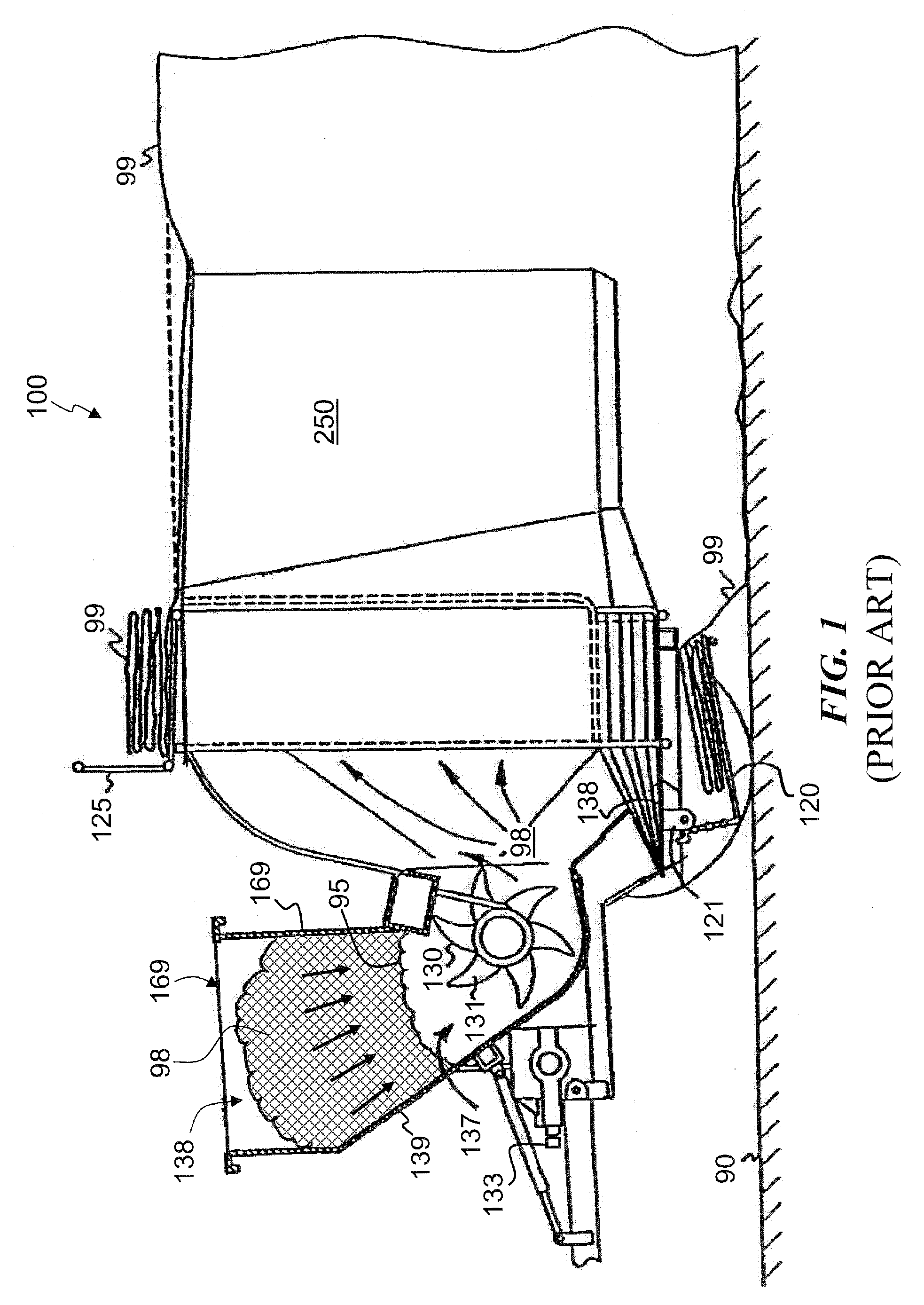
[0038]FIG. 1 is a side view of a prior-art bagging machine 100 whereby feed 96 is deposited into hopper 138 and moves downward along slopi...


PUM

PropertyMeasurementUnit
diameteraaaaaaaaaa
diameteraaaaaaaaaa
diameteraaaaaaaaaa

Abstract

An agricultural bagger apparatus and method for compacting feed into a horizontally deployed bag including a compression mechanism and an input hopper that receives agricultural feed. The hopper has a sloping wall and a lower end exit chute located to transfer the feed into the primary compression mechanism (e.g., a rotating toothed cylinder). The tapered hopper causes the feed to bridge, stopping the feed from falling through the chute. A new distribution mechanism in the hopper sweeps the feed adjacent to the sloping wall to prevent feed bridging. By preventing the feed from clogging, there is less reason to risk one's safety by foolishly inserting their limb into the hopper. Some embodiments also compact feed in the upper portion of the tunnel, for example, by reciprocating a hinged piston above the primary compression mechanism. This increases the compaction on the top portion of the tunnel without unduly juicing the feed.

Description

CROSS-REFERENCE TO RELATED APPLICATIONS [0001] This is a continuation of, and claims benefit of, U.S. patent application Ser. No. 09 / 977,036, Filing Date Oct. 11, 2001, now U.S. Pat. No. 7,024,839, issued Apr. 11, 2006, which is hereby incorporated by reference in its entirety.FIELD OF THE INVENTION [0002] This invention relates to the field of agricultural baggers, and more specifically to a method and apparatus of displacing pressure in the upper tunnel and for preventing bridging of feed in the input chute. BACKGROUND OF THE INVENTION [0003] Horizontally expandable, silage storage bags are commonly used as an alternative to permanent feed storage structures such as barns and silos. From an economic standpoint, an expandable plastic storage bag is preferable to a more elaborate, permanent structure. Further, the expandable bags are more easily loaded with feed than permanent structure and the silage stored therein is readily accessible for use, for example using a small tractor wi...

Claims


Application Information

Patent Timeline
Patent Type & Authority Applications(United States)
IPC IPC(8): B65B63/02B65B43/26B65B9/10A01F25/14
CPCA01F25/14A01F2025/145A01F25/183B30B9/301
Inventor WINGERT, PAUL
Owner WINGERT PAUL
Learn More