
Surgical holding device

a technology of holding device and surgical instrument, which is applied in the direction of mechanical control device, instrument, application, etc., can solve the problem of narrow restriction of the radius of action of the surgical instrumen

Inactive Publication Date: 2006-10-12
RWTH AACHEN UNIVERSITY +1
View PDF6 Cites 23 Cited by
  • Summary
  • Abstract
  • Description
  • Claims
  • Application Information

AI Technical Summary

Benefits of technology

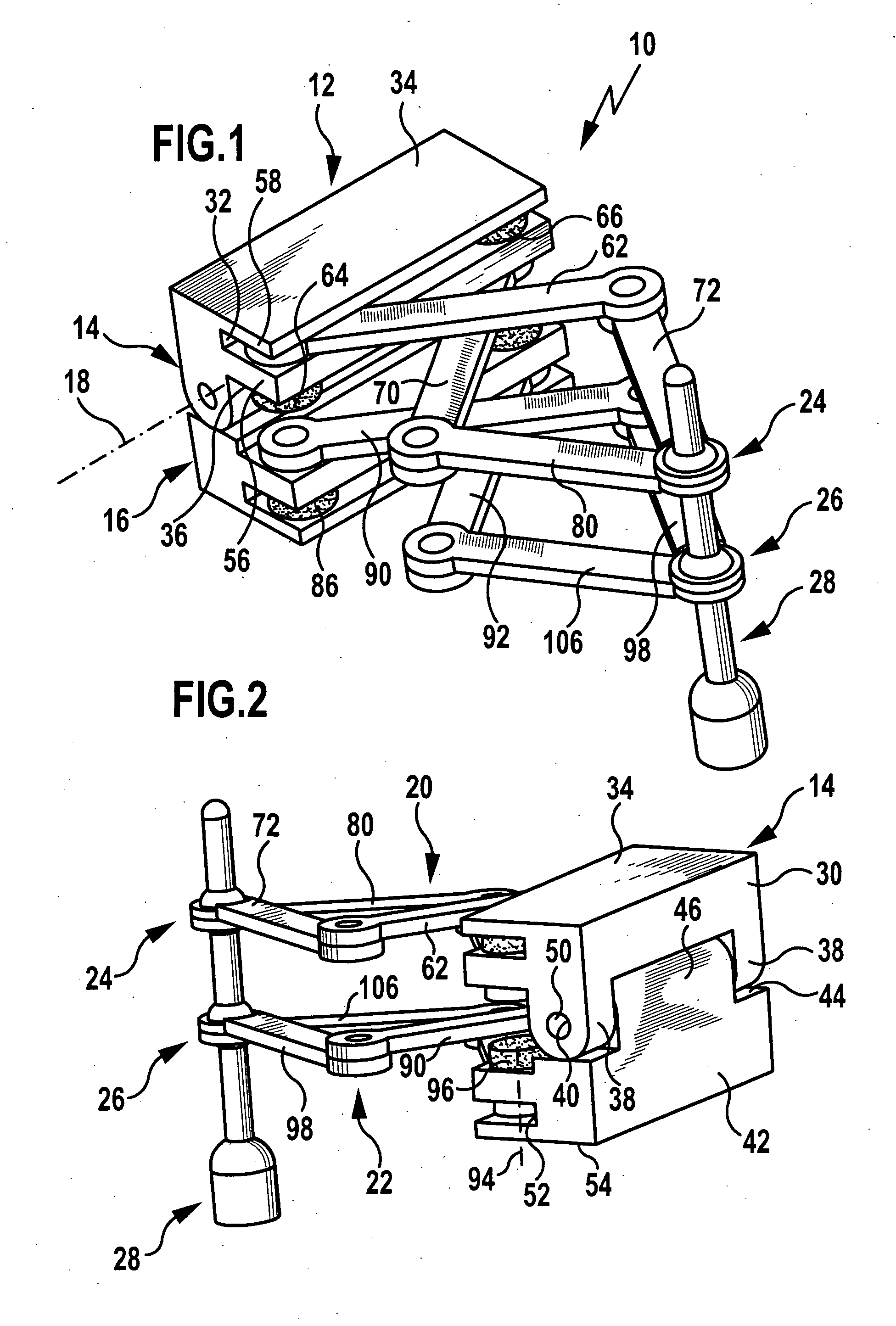
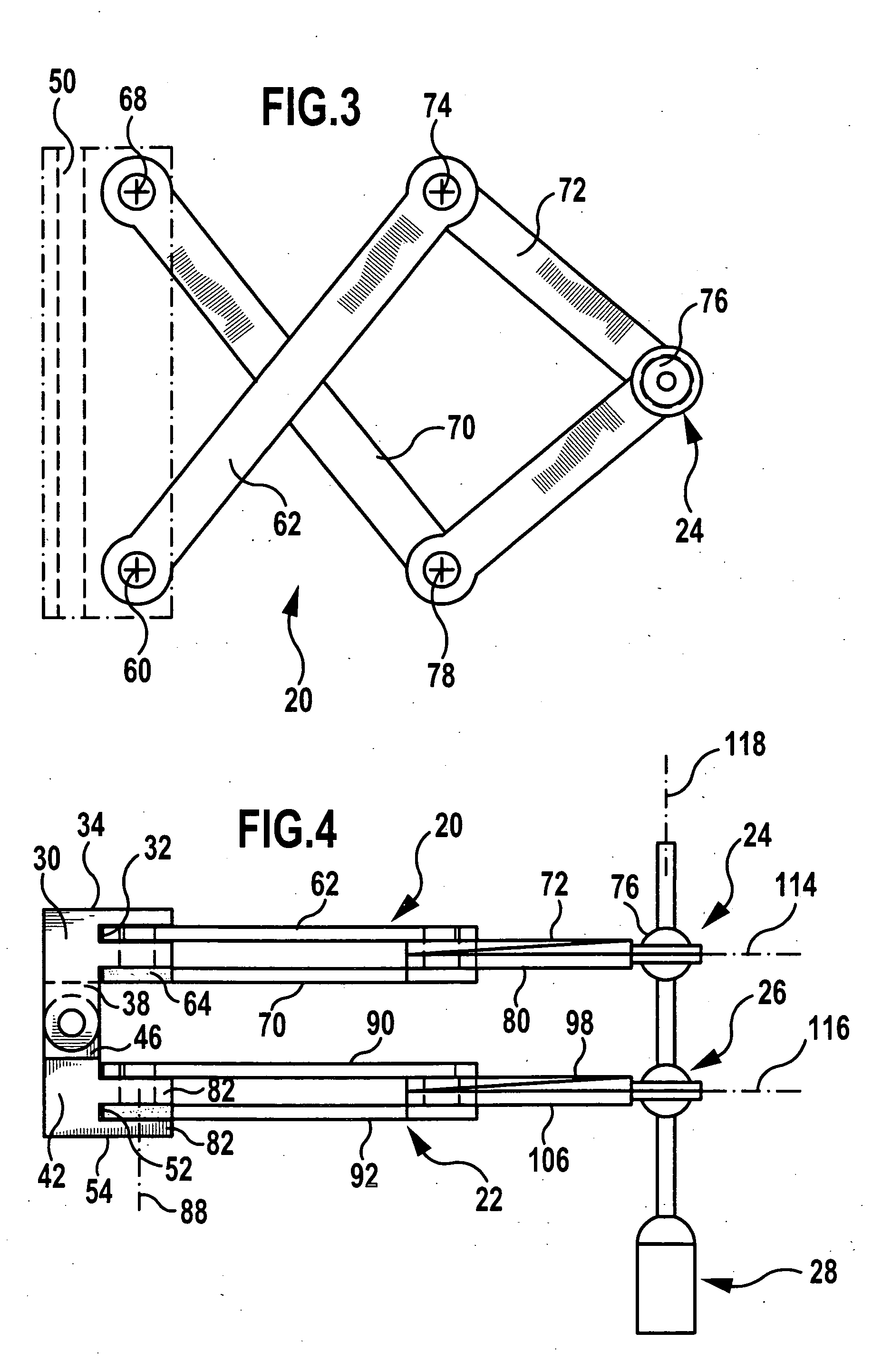
[0006] This object is accomplished, in accordance with the invention, with a surgical holding device of the kind described at the outset in that the links of the first linkage are mounted for pivotal movement about pivot axes relative to one another and relative to the frame, and in that the pivot axes extend parallel to one another. In accordance with the proposed arrangement, all links are adjustable in their position relative to the frame, i. e., also a link held on the frame is mounted pivotably relative to the frame. In this way, the first articulation point is movable within a range of action which comprises a maximum area with a maximum side length, which corresponds to a total length of the links arranged one behind the other. The parallel arrangement of the pivot axes also enables a movement of the first articulation point in a plane.

Problems solved by technology

Translational drives have the disadvantage that they are relatively large and heavy, so that the fixed actuator must be of particularly stable construction.
Furthermore, with the known device the two articulation points are only positionable within a very narrowly limited range, i. e., a radius of action of the surgical instrument is narrowly restricted.

Method used


Image

  • Surgical holding device
  • Surgical holding device
  • Surgical holding device

Examples


Embodiment Construction

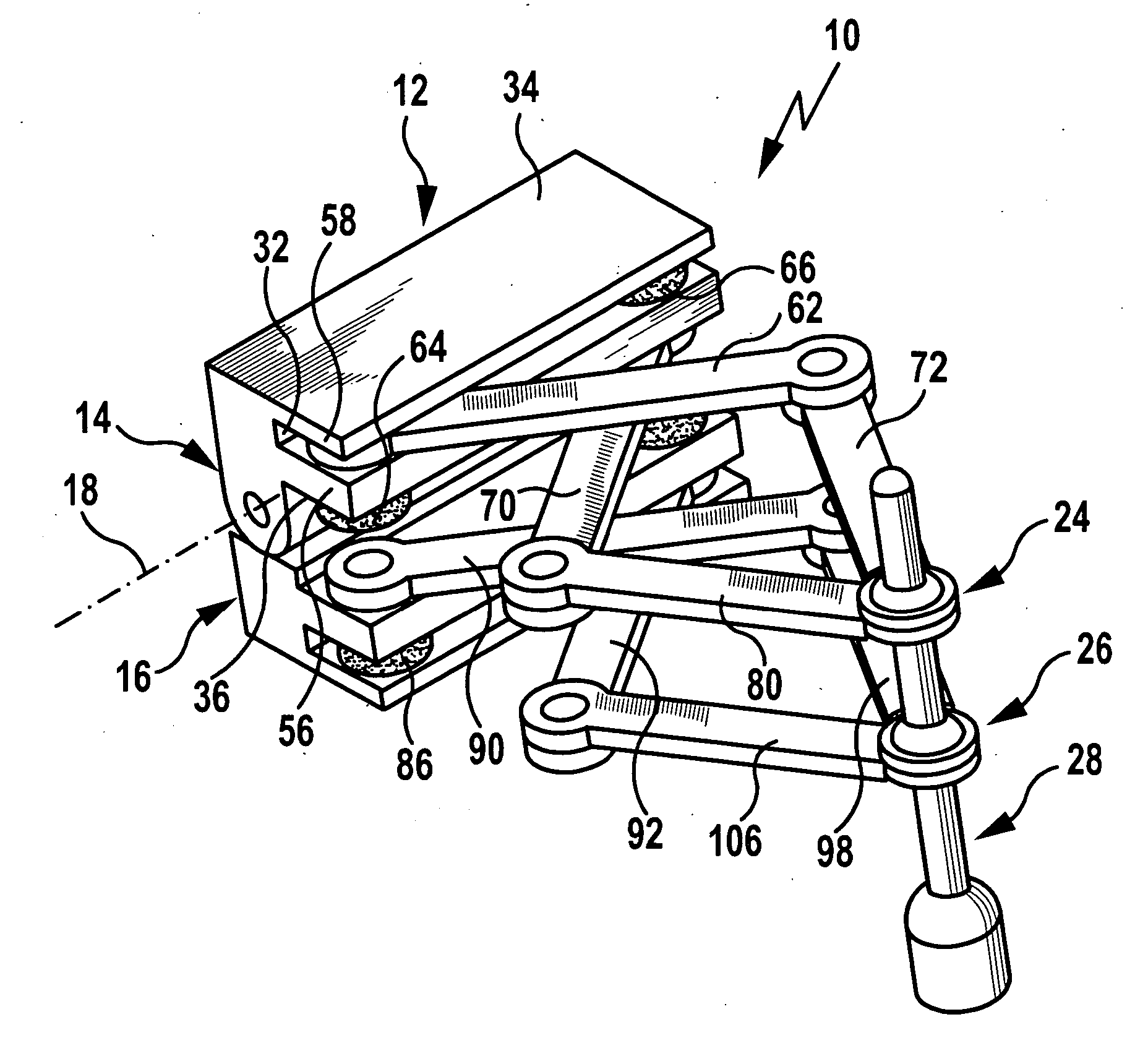
[0050] A motor-driven platform for supporting equipment, which can be coupled as a module to various surgical holding systems, is generally designated by reference numeral 10 in FIGS. 1 to 6. It comprises a two-part frame 12 with an upper frame half 14 and a lower frame half 16 mounted for pivotal movement about a frame pivot axis 18 relative to the upper frame half 14. There is associated with each of the two frame halves 14 and 16 a five-member crank mechanism 20 and 22, respectively. In the present embodiment, the crank mechanisms are of identical design. Furthermore, each of the two crank mechanisms 20 and 22 carries an articulation point 24 and 26, respectively, at which a surgical instrument 28, for example, in the form of a milling tool or an optical endoscope, is held.

[0051] The upper frame half 14 comprises a main body 30 of rectangular parallelepiped construction having on one of its narrow long sides a longitudinal groove 32 arranged in parallel with a top side 34 of the...


PUM


Abstract

In order to improve a surgical holding device for holding a surgical instrument, with a frame, with a first linkage comprising at least two links, which articulatedly connects the frame to a first articulation point associated with the instrument, and with a second linkage comprising at least two links, which articulatedly connects the frame to a second articulation point associated with the instrument, so that a large range of action of the surgical instrument held by the holding device is adjustable as simply as possible, it is proposed that the links of the first linkage be mounted for pivotal movement about pivot axes relative to one another and relative to the frame, and that the pivot axes extend parallel to one another.

Description

[0001] This application is a continuation of international application number PCT / EP2004 / 006209, filed on Jun. 9, 2004. [0002] The present disclosure relates to the subject matter disclosed in international application number PCT / EP2004 / 006209 of Jun. 9, 2004 and German application number 103 40 151.2 of Aug. 26, 2003, which are incorporated herein by reference in their entirety and for all purposes.BACKGROUND OF THE INVENTION [0003] The invention relates to a surgical holding device for holding a surgical instrument, with a frame, with a first linkage comprising at least two links, which articulatedly connects the frame to a first articulation point associated with the instrument, and with a second linkage comprising at least two links, which articulatedly connects the frame to a second articulation point associated with the instrument. [0004] Such a holding device is known, for example, from US 2002 / 0038118 A1. This comprises two actuators rigidly connected to a base and two actua...

Claims


Application Information

Patent Timeline
Patent Type & Authority Applications(United States)
IPC IPC(8): G05G1/00A61B19/00F16M11/38
CPCA61B19/26F16M11/38Y10T74/20F16M13/02F16M2200/061F16M11/048A61B90/50
Inventor FISCHER, MANFREDLUTZE, THEODORRADERMACHER, KLAUSHAHNDORFF, MARKUSLAUER, WOLFGANG
Owner RWTH AACHEN UNIVERSITY
Learn More