
Housing For An Inertial Switch

Inactive Publication Date: 2012-07-26
SLOTZNICK BENJAMIN
View PDF5 Cites 3 Cited by
  • Summary
  • Abstract
  • Description
  • Claims
  • Application Information

AI Technical Summary

Benefits of technology

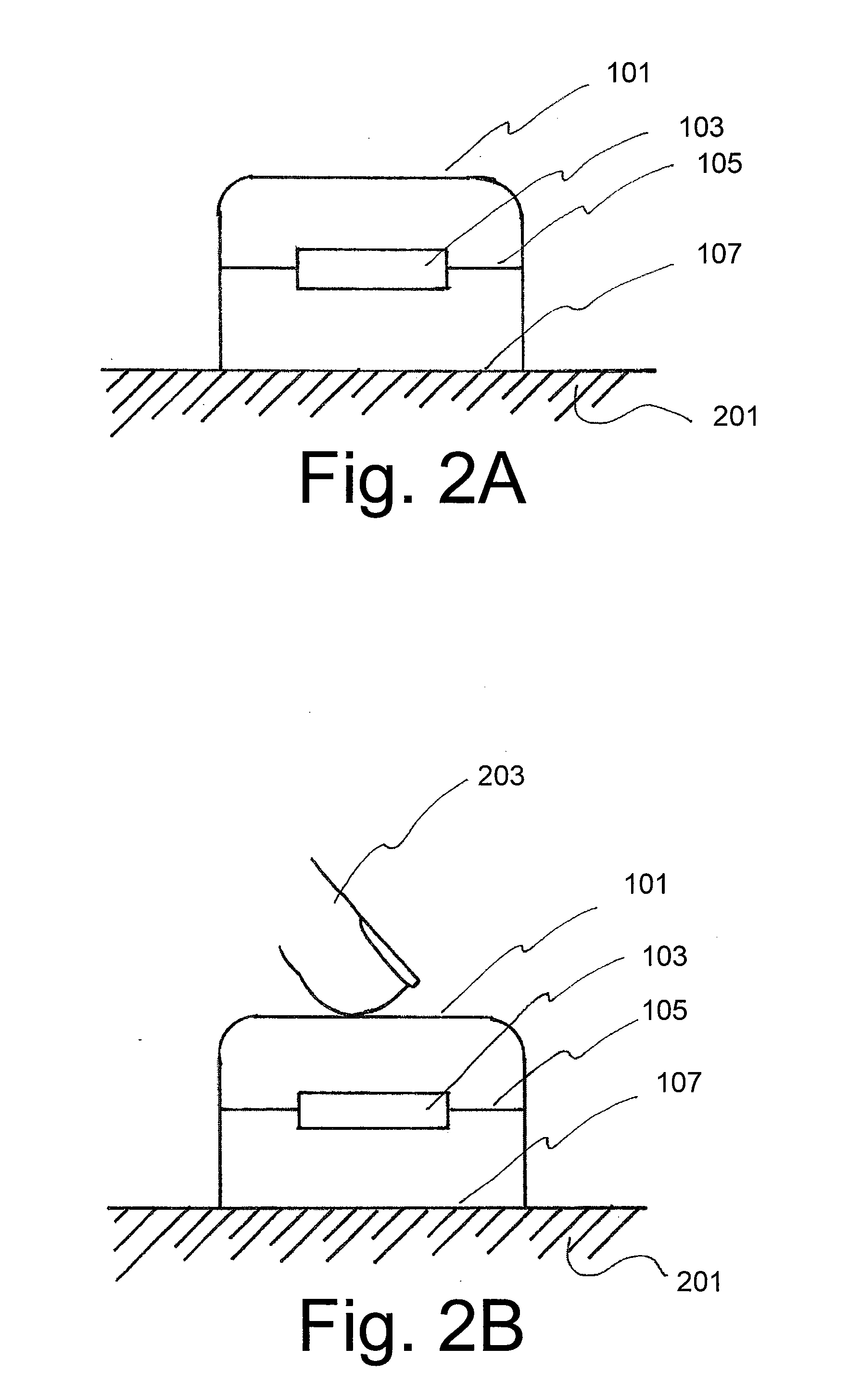
[0017]In another preferred embodiment, a kink, bend, or deformation in the housing circles the outside of the housing of the device, on the sides or along the periphery of the device. This kink, bend, or deformation is placed between the portion of the housing that rests on the immovable surface and the rest of the housing to which the accelerometer is attached. This kink, bend, or deformation introduces flex to that portion of the housing, as is well known in the material fabrication arts, thus enabling movement of the accelerometer inside the device when the device is pushed against the immovable surface.
[0018]In alternative embodiments, the kink, bend or deformation has different cross-sections. Alternate embodiments use, multiple kinks, bends, or deformations. Still other alternate embodiments use combinations of kinks, bends, and deformations. Other embodiments use combinations of different kinds, bends and deformations. The kink(s), bend(s), and deformation(s) are functional but to many people appear as a decorative aspect of the housing. In an alternative embodiment, springs or sprung legs are placed on the “bottom” of the device housing, so that when the device is placed upon the immovable surface, it rests on these legs. This enables movement of the accelerometer inside the device when the device is pushed against the immovable surface.
[0023]In these various embodiments the accelerometer (or accompanying circuitry or software) can be designed to register the action of pressing-a-portion-of-the-device as a switching action. Alternatively the accelerometer (or accompanying circuitry or software) can be designed to register the action of releasing-the-device (after the pressing-a-portion-of-the-device has occurred) as a switching action. Alternatively it can be designed such that a tap (combined pressing and releasing action that occurs in a short time) is the switching action. In an alternative embodiment, a double tap (or other multiple tap) is the switching action.

Problems solved by technology

In contrast, tapping or pushing down on a solid device that rests on a hard surface (such as a table or desk), would not be expected to elicit a change in an accelerometer built into the device, so that tapping or pushing down on the device could not be coupled with the accelerometer as a switch for device functions.
Zwart et al. does not disclose how to detect when one object is very near the surface of another object, or gently touching the surface, or gently swiping along a surface.
Zwart et al. also does not disclose how to detect when one object (which has been near or gently touching another object) moves away from that second object.
Zwart et al. also does not disclose how to detect when one object gently, though possibly with great force, pushes on the surface of another object—or then releases that force.
Two different kinds of switching events are required of many control devices, and thus unitary event detection has inherent limitations.
Furthermore, the unitary event detection in Zwart et al. and Cradick et al. fails to capture more granular information, such as where on a surface did the user tap (e.g., left or right side, center or corner).
Holbein et al. does not disclose what inertial event (if any) will be caused by the release of pressure, or how that event will be affected by the fact that the user may be holding the device in his or her hand, which will react to the release in pressure with motion of its own.

Method used


Image

  • Housing For An Inertial Switch
  • Housing For An Inertial Switch
  • Housing For An Inertial Switch

Examples


Embodiment Construction

[0049]Certain terminology is used herein for convenience only and is not to be taken as a limitation on the present invention.

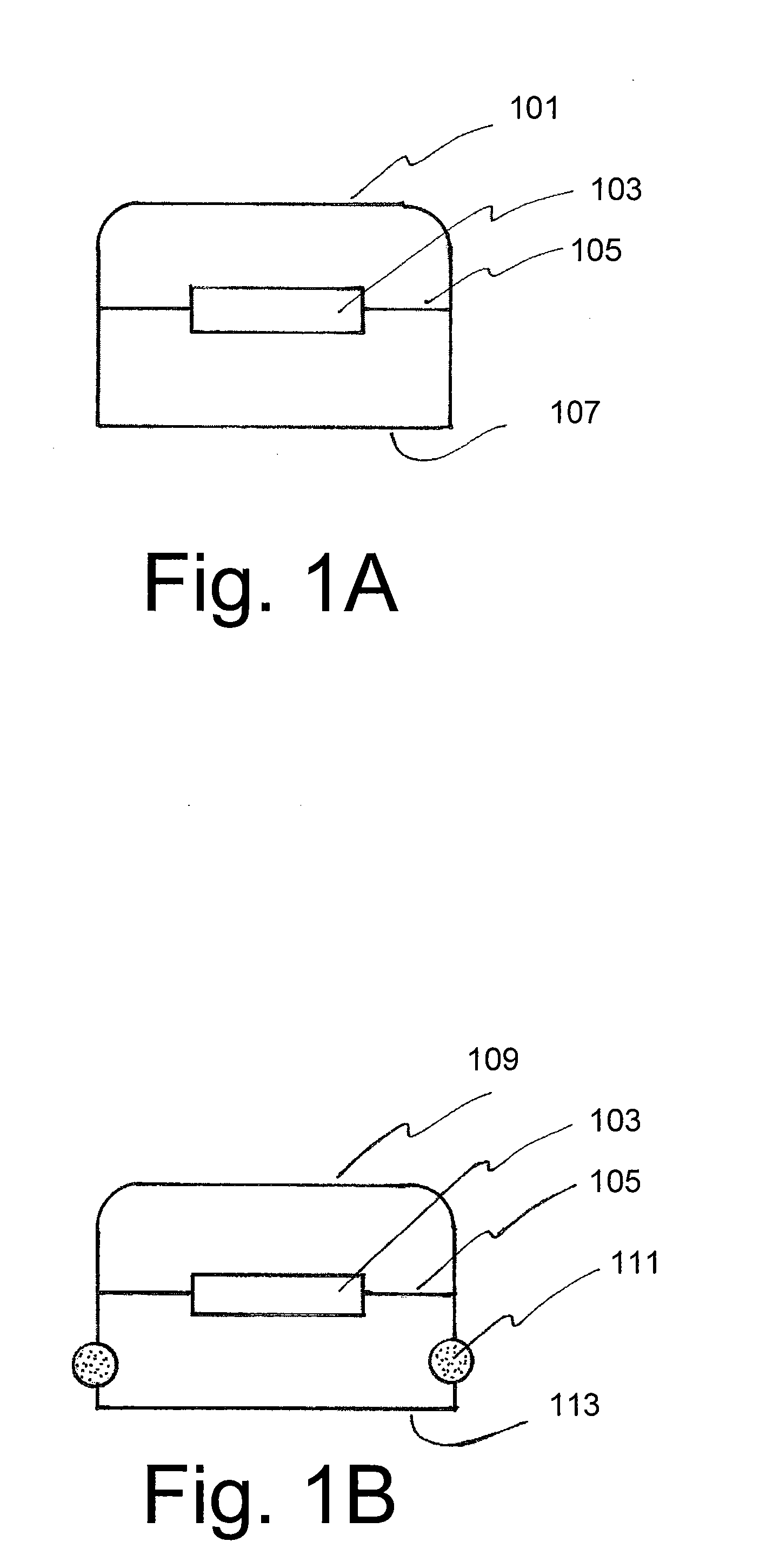
[0050]FIG. 1A is a cross-section of a device that incorporates an accelerometer, but does not embody this invention. It is most easy to visualize this figure as representing a cellular telephone or an MP3 player. However similar figures with the same components, but at different scales could be drawn to represent other devices with accelerometers. The device has a rigid casing or housing 101. If you set it down on a table, a portion of the casing 107 would be the part placed against the table. In this figure one thinks of 107 as the bottom of the device, but that would be as accurate in a similar figure in which 107 is not a straight line. The device also includes an accelerometer 103 which is attached at 105 to the housing so that movements in the housing would move, affect, and register with the accelerometer.

[0051]In contrast to FIG. 1A, FIG. 1B is a cross...


PUM


Abstract

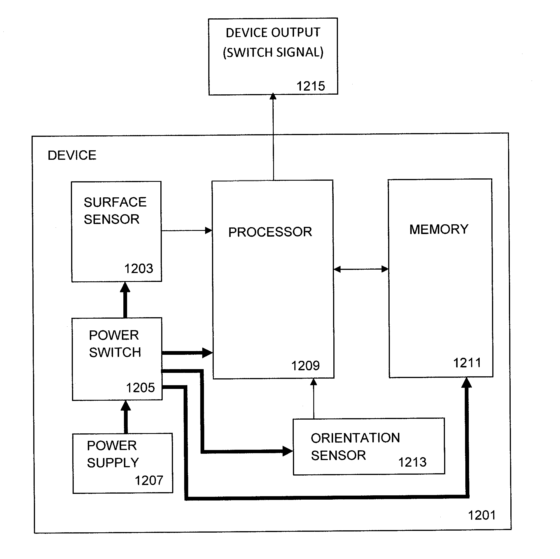
An apparatus that provides switch signals includes an upper portion, a lower portion, compressible material disposed between the upper portion and the lower portion, memory and a processor. The upper portion includes an outer surface having portions that define at least two different regions. At least one of the different regions has a switch function. The upper portion also includes a three-dimensional orientation sensor that generates three-dimensional orientation signals in response to movement of the upper portion. The lower portion has a bottom surface adapted to be placed against an immovable surface. The memory electronically stores information regarding the portions of the outer surface that define at least one region having a switch function. The processor includes processor logic that uses the electronically stored information in the memory and the orientation signals to detect whether a region having a switch function was pressed, and if so, outputs a switch signal.

Description

CROSS-REFERENCE TO RELATED APPLICATION[0001]This application claims the benefit of U.S. Provisional Patent Application No. 61 / 436,308 filed Jan. 26, 2011, which is incorporated in its entirety herein.BACKGROUND OF THE INVENTION[0002]Many devices include components which sense a change in their orientation with respect to gravity and inertia. These components have many names and methods of construction. Names include gyroscopes, accelerometers, inclinators, and tilt sensors. The methods include mechanical gyroscopic devices, electronic sensors, piezoelectric sensors, capacitive sensors, microelectromechanical systems (MEMS), arrays of force sensing transducers (including force sensing resistors), and even nanodevices. The term “accelerometer” as used herein refers generically to any one of these devices (even if not a true accelerometer), without limitation as to specific technology and methodology used. In this disclosure, the term “orientation sensor” is used to refer to a sensor o...

Claims


Application Information

Patent Timeline
IPC IPC(8): H03K17/965
CPCH03K17/965G06F1/1694G01P15/00
Inventor SLOTZNICK, BENJAMIN
Owner SLOTZNICK BENJAMIN
Learn More