

Electric wire, electric wire connection method and wire harness
a technology of electric wire and connection method, which is applied in the direction of cables, insulated conductors, conductors, etc., to achieve the effect of easy recognition
- Summary
- Abstract
- Description
- Claims
- Application Information
AI Technical Summary
Benefits of technology
Problems solved by technology
Method used
Image

Examples
first embodiment
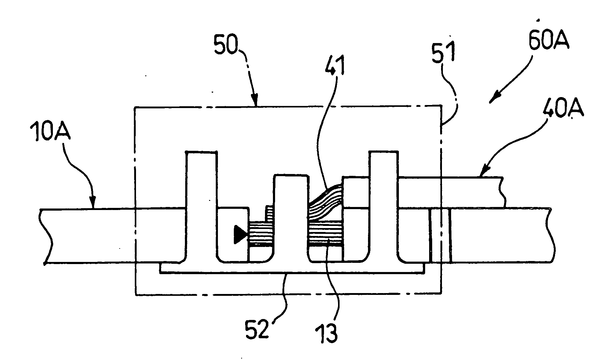
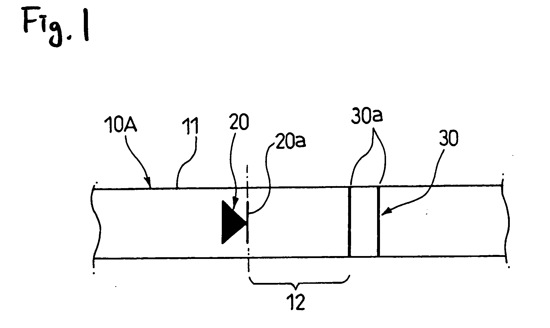
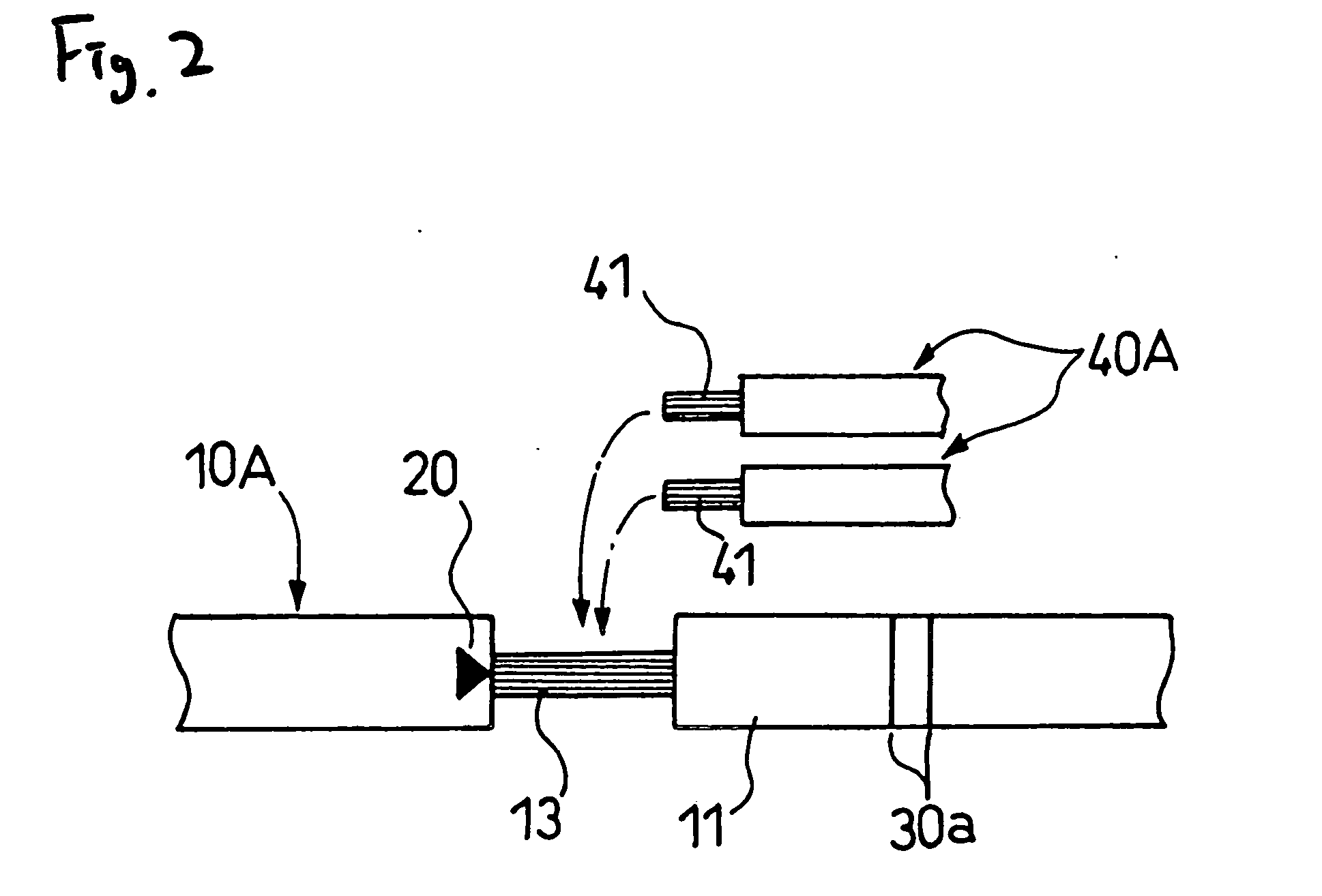
[0034] As shown in FIG. 1, in the wire 10A serving as a first wire according to the present invention, a first marking 20 and a second marking 30 are provided on a covering sheath 11, and are arranged at a predetermined interval. The first marking 20 indicates an operation position. More specifically, the first marking 20 indicates that the operation position lies between the first marking 20 and the second marking 30, and this first marking has a portion 20a indicating one end limit of an operation range 12.
[0035] On the other hand, the second marking 30 indicates the other end limit of the operation range 12, and also indicates an operation form.
[0036] As shown in FIG. 2, two rings 30a, 30a are provided, and the ring 30a indicates that contents of the operation are the operation for connecting branch wires 40 which are second wires. At the same time, the provision of the two rings 30a indicates that the number of branch wires 40A to be connected is two.
[0037] Therefore, in the w...
second embodiment
[0043] As shown in FIG. 4, a plurality of (here, three) pairs of first markings 21a, 21b, 21c and second markings 31a, 31b, 31c are provided on a covering sheath 11 of the wire 10B of the present invention. Each of the first markings 21a, 21b, 21c indicates that an operation position lies between the first marking and the corresponding second marking 31 a, 31 b, 31c, and also each first marking has a portion indicating one end limit of an operation range 12a, 12b, 12c.
[0044] The second markings 31a, 31b, 31c have respective described rings 32, and therefore each operation form is a connecting operation. Two rings 32 are described only at the central marking 31 b, and therefore it will be appreciated that there are two branch wires 40B to be connected.
[0045] At the same time, a mark 22, described at the first marking 21, corresponds to a mark 33 described at an end-adjacent portion of the branch wire 40B which is to be connected relative to this first marking 21.
[0046] For example...
third embodiment
[0052] As shown in FIG. 5, a first marking 23 and a second marking 34 are provided on a covering sheath 11 of the wire 10C of the present invention. The first marking 23 has a hatching of a predetermined width, and indicates an operation range 12. The second marking 34 consists of two arrows 34a, 34a, and indicates that the number of branch wires (not shown) to be connected to the wire 10C is two and that the branch wires should are installed from the right. Therefore, the branch wires are installed in the right direction from the hatching portion defining the operation range 12.
[0053] The wire connecting method of connecting the wire 10C and the branch wires together at the operation position 12 is totally identical to that described above for the first embodiment, and therefore explanation thereof is omitted.
[0054] As described above, in the above-mentioned wire, the wire connecting method and wire harness, the operation is carried out according to the contents described at the f...
PUM
 Abstract
Description
Claims
Application Information