Mounting method of clip and weather strip

a technology of mounting method and weather strip, which is applied in the direction of roofs, doors, transportation and packaging, etc., can solve the problems of not meeting the recent demands for weight saving, the above-mentioned extrusion-molding of the partially altered weather strip b>10/b> depending on the thickness of the flange b>100/b> is complicated, and the remaining parts of the weather strip which do not sufficiently correspond, etc., to achieve the a weather strip and clip and weather strip and clip and weather strip and clip and weather strip and clip weather strip clip and weather strip and mounting method is applied in the field of clip and weather strip and the technology of clip and the weather strip and the weather strip and the the weather strip and the weather strip is not suitable for the weather strip

Inactive Publication Date: 2006-10-12
NISHIKAWA RUBBER
View PDF4 Cites 8 Cited by
  • Summary
  • Abstract
  • Description
  • Claims
  • Application Information

AI Technical Summary

Benefits of technology

[0022] As mentioned above, the structure of the clip is not complicated and the clip enables the weather strip to be mounted on the flange only by rotating or moving the pressuring piece of the clip so that the mounting operation is accomplished in a short time. Additionally, the use of the resin insert enables weight saving and recyclability.
[0023] Further, according to the mounting method of the weather strip of the present invention, the clip is mounted on the installation base member of the weather strip through the fixing piece while the pressuring piece is separated from the surface of the cabin side of the flange by the rotation or movement, therefore, the pressuring piece does not interfere the mounting. Then, the installation surface of the installation base member with the clip is mounted on the surface of the outer-cabin side of the flange, and the pressuring piece is rotated or moved to approach the surface of the cabin side of the flange thereby making the elastic contact so that the pressuring piece holds the flange with the installation surface of said installation base member, therefore, the mounting is easily accomplished in a short time.
[0024] Moreover, according the mounting method of the weather strip of the present invention, the clip is mounted on one end of the resin insert exposed from the installation base member of the weather strip through the fixing piece while the pressuring piece is separated from the surface of the cabin side of the flange by the rotation or movement, therefore, the pressuring piece does not interfere the mounting. Then, the installation surface of the installation base member with the clip is mounted on the surface of the outer-cabin side of the flange, and the pressuring piece is rotated or moved to approach the surface of the cabin side of the flange thereby making the elastic contact so that the pressuring piece holds the flange with the installation surface of the installation base member, therefore, the mounting is easily accomplished in a short time.

Problems solved by technology

But the above-mentioned extrusion-molding of the partially altered weather strip 10 depending on the thickness of the flange 100 is complicated.
In addition, there may remain parts on the weather strip which do not sufficiently correspond to the shape of the flange 100.
Further, the extrusion-molding of the cross-section roughly U-shaped installation base member 12 does not satisfy the recent demands for weight saving of the weather strip 10.
Especially, when the core metal 14 is used, the weight of the weather strip further increases and the demands for recycling are not satisfied.
Thus, the above-mentioned Publication does not disclose the weight saving of the weather strip.
Therefore, the clip is complicated in structure and is difficult to mount.

Method used


Image

  • Mounting method of clip and weather strip
  • Mounting method of clip and weather strip
  • Mounting method of clip and weather strip

Examples


Embodiment Construction

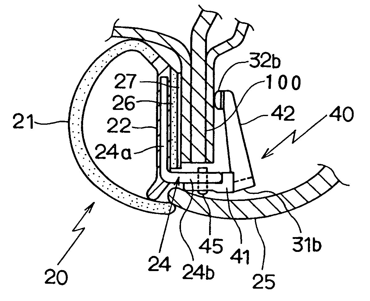
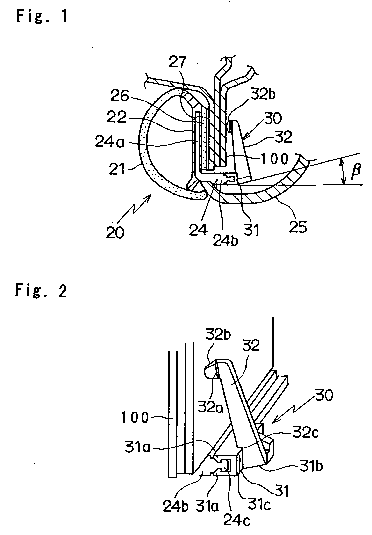
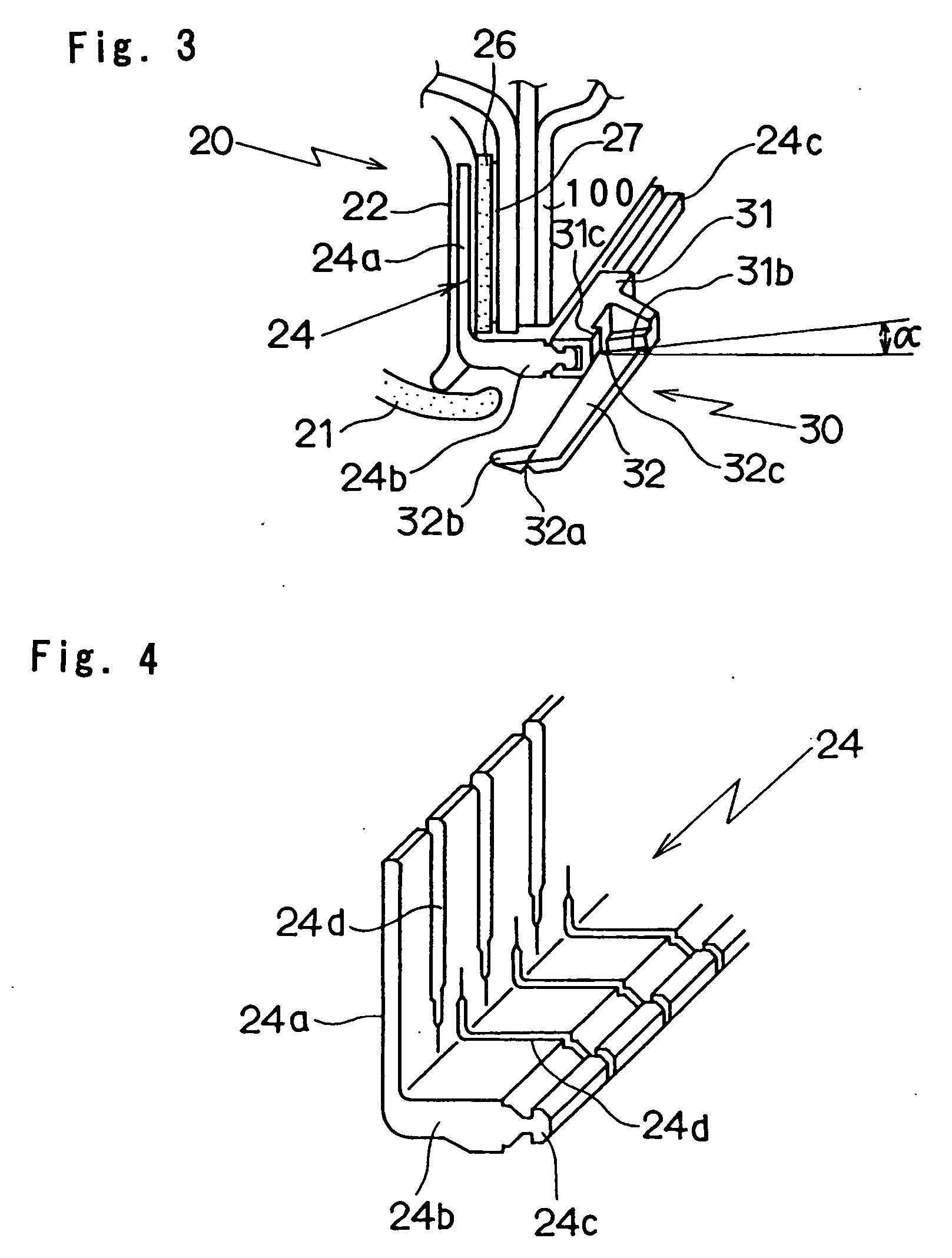
[0043] Referring to FIGS. 1 to 4, a clip according to an embodiment of the invention and mounting method of a weather strip by means of the clip will be described.

[0044] A clip 30 is used for mounting an installation base member 22 of a weather strip 20 on a flange 100 exposed from a body of an automobile.

[0045] The weather strip 20 is composed of the installation base member 22 made of solid rubber and a hollow seal member 21 made of rubber sponge for conducting an elastic contact with a door and sealing both outer-side and inner-side of the automobile when the door (not shown) is opened or closed.

[0046] The installation base member 22 is roughly straight in section and both of end portions thereof are equipped with base roots of the hollow seal member 21. Generally, the installation base member 22 roughly forms U shape in section so as to cover the flange 100. But, the shape of the installation base member 22 of the present invention corresponds to the shape of a side surface w...


PUM


Abstract

There is provided a clip 30 for mounting an installation base member 22 of a weather strip 20 on a flange 100 provided along a body of an automobile, wherein said clip 30 is composed of a fixing piece 31 mounted on an exposed end portion of a resin insert 24 embedded in the installation base member 22 of said weather strip 20; and a pressuring piece 32 which is rotatably mounted to the fixing piece 31, approaches one side surface of said flange 100 by the rotation to make an elastic contact, and holds said flange 100 with an installation surface of said installation base member 22 mounted on the other side surface of said flange 100.

Description

BACKGROUND OF THE INVENTION [0001] The present invention relates to a mounting method of a clip for mounting an installation base member of a weather strip on a flange provided along a body of an automobile and a mounting method of the weather strip using the clip. [0002] In mounting a weather strip 10 on a flange 100 provided along a body of an automobile, in usual, plural protuberances 13 are formed inside sidewalls of a cross-section roughly U-shaped installation base member 12 with which a hollow seal member 11 is integrally molded so that a flange 100 is held making use of elasticity of the protuberances 13 as shown in FIG. 17. In addition, a core metal 14 which also roughly forms U shape in section is embedded inside the installation base member 12 in order to improve holding force of the protuberances 13 toward the flange 100. Cabin side of the installation base member 12 is covered with an interior material 15. [0003] Generally, thickness of the flange 100 is not even and th...

Claims


Application Information

Patent Timeline
Patent Type & Authority Applications(United States)
IPC IPC(8): B60J10/08B60R13/06
CPCB60J10/0062B60J10/0088F16B5/121B60R13/06B60J10/08B60J10/30B60J10/45B60J10/80
Inventor SAITO, KATSUSHI
Owner NISHIKAWA RUBBER
Why Eureka
Try Eureka