
Drive control device for use in an image forming apparatus

Active Publication Date: 2006-10-12
HEWLETT PACKARD DEV CO LP
View PDF1 Cites 9 Cited by
  • Summary
  • Abstract
  • Description
  • Claims
  • Application Information

AI Technical Summary

Benefits of technology

[0011] Various aspects and example embodiments of the present invention provide a new drive control device for use in an image forming apparatus which can inexpensively control the drive of a laser scanning unit (LSU) and one or more driving motors.

Problems solved by technology

Conventional power switching devices can be costly to install, and can drive the cost of such an image forming apparatus unnecessarily.
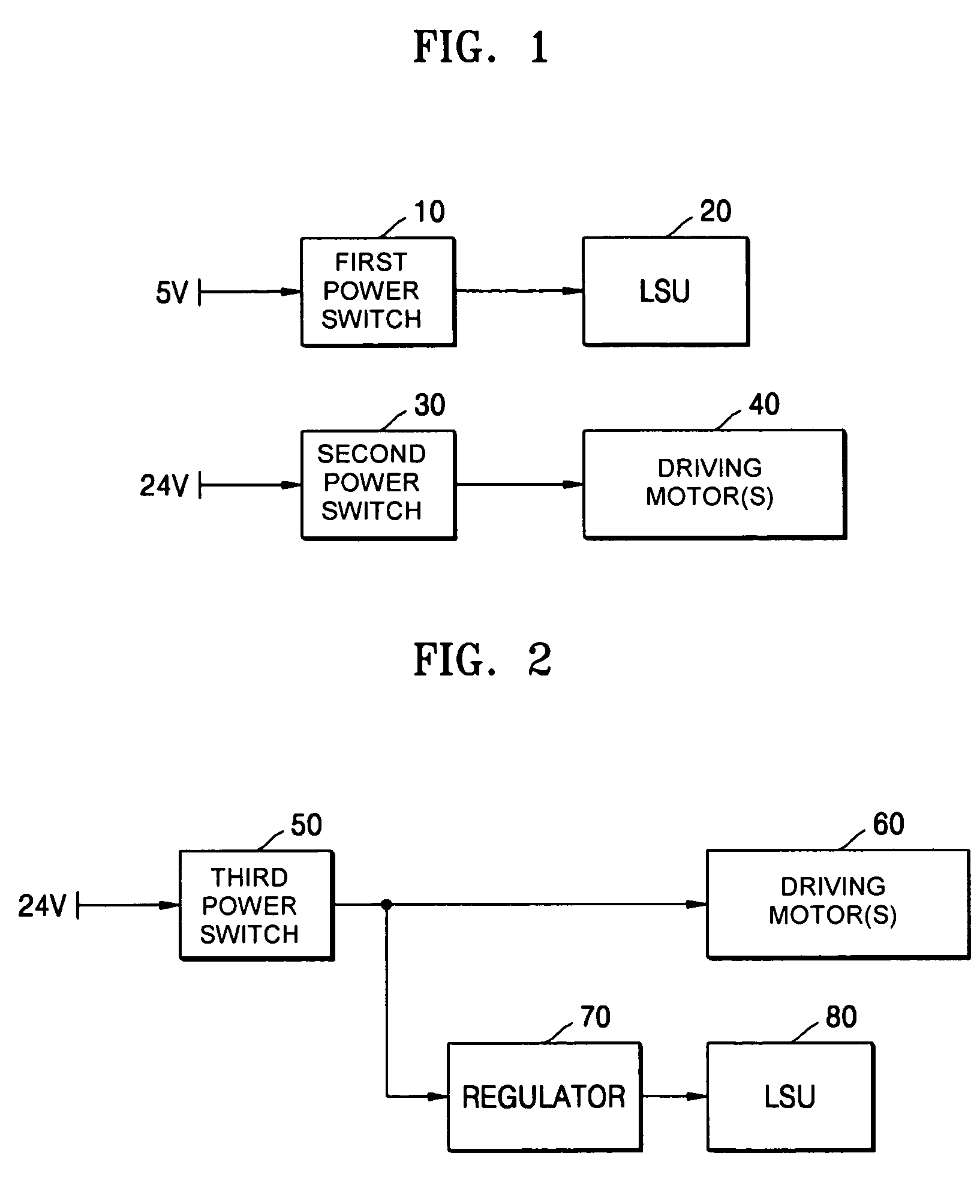
If two mechanical switches are used, as shown in FIG. 1, or a single mechanical switch and a regulator are used as shown in FIG. 2, cost of the device for controlling the laser scanning unit and the one or more driving motors in an image forming apparatus increases.

Method used


Image

  • Drive control device for use in an image forming apparatus
  • Drive control device for use in an image forming apparatus
  • Drive control device for use in an image forming apparatus

Examples


Embodiment Construction

[0025] Reference will now be made in detail to the present embodiments of the present invention, examples of which are illustrated in the accompanying drawings, wherein like reference numerals refer to the like elements throughout. The embodiments are described below in order to explain the present invention by referring to the figures.

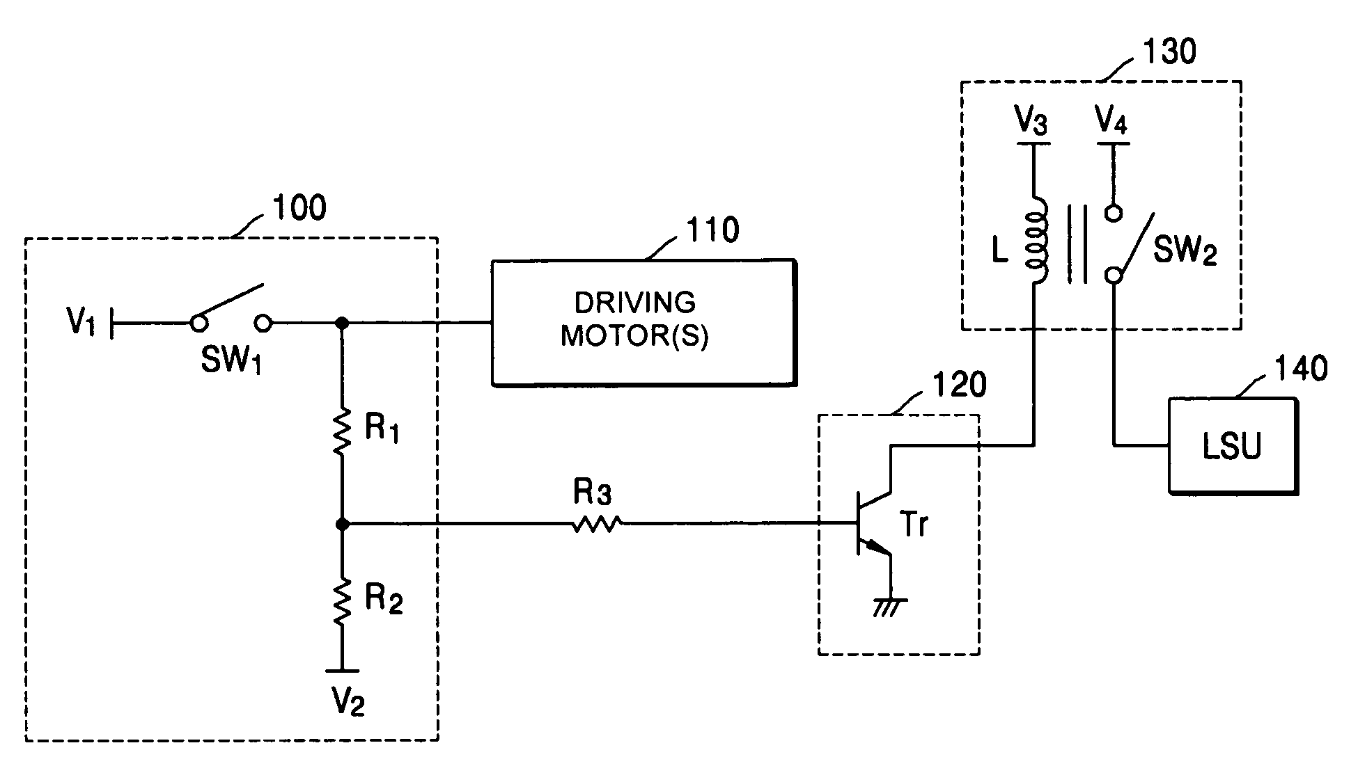
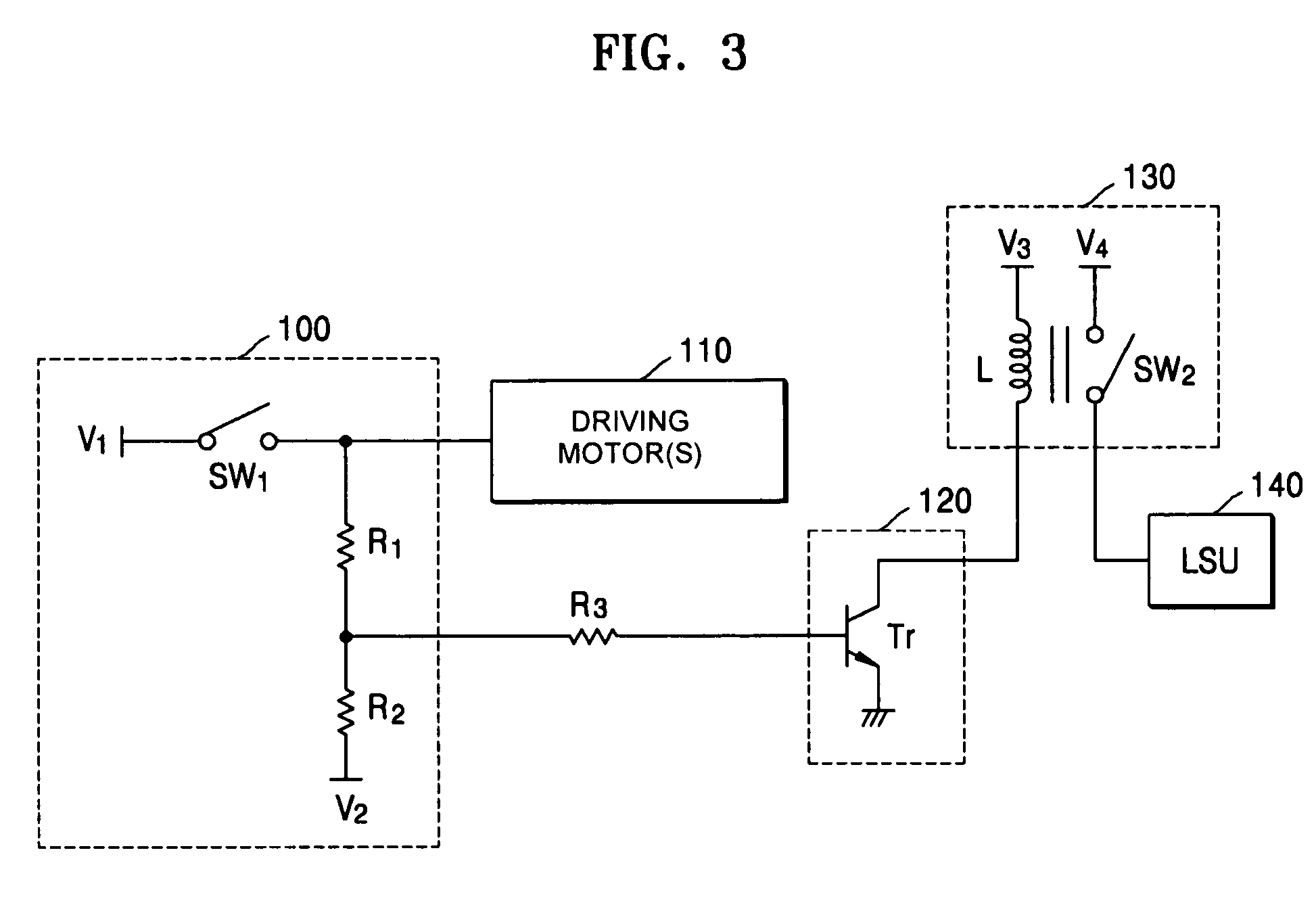
[0026]FIG. 3 is a block diagram of an example drive control device for use in an image forming apparatus according to an embodiment of the present invention. As shown in FIG. 3, the drive control device includes a cover sensing unit 100, one or more driving motors 110, a relay operation control unit 120, a relay unit 130, and a laser scanning unit 140.

[0027] The cover sensing unit 100 detects the opening of a cover (not shown) of the image forming device, and outputs the detected result to the relay operation control unit 120.

[0028] The cover sensing unit 100 detects that the cover is opened, when a voltage for driving the one or more driving motor...


PUM


Abstract

A drive control device for use in an image forming apparatus comprises: a cover sensing unit which detects the opening of a cover of the image forming apparatus; a relay unit which controls supplement of a voltage for driving a laser scanning unit; and a relay operation control unit which controls the operation of the relay unit in response to the detected result of the cover sensing unit. Accordingly, the drive control device of the image forming apparatus can control operation of one or more driving motors and the laser scanning unit at low cost.

Description

CROSS-REFERENCE TO RELATED APPLICATIONS [0001] This application claims all benefits accruing under 35 U.S.C §119 from Korean Patent Application No. 10-2005-0023652, filed on Mar. 22, 2005, in the Korean Intellectual Property Office, the disclosure of which is incorporated by reference herein. BACKGROUND OF THE INVENTION [0002] 1. Field of the Invention [0003] The present invention relates to an image forming apparatus, and more particularly, to a drive control device for controlling the drive of an image forming motor and a laser scanning unit in an image forming apparatus. [0004] 2. Related Art [0005] In general, an image forming apparatus, such as, a printer, a facsimile machine, a photocopier and a multi-functional product, is typically provided with an engine driving unit, a laser scanning unit, and a control unit operable with a control panel. Typically, the engine driving unit is provided with one or more driving motors for driving one or more components, such as a conveying u...

Claims


Application Information

Patent Timeline
IPC IPC(8): H02P7/00
CPCG03G15/55G03G15/5004G03G21/145G03G21/1633
Inventor YOO, SI-HUN
Owner HEWLETT PACKARD DEV CO LP
Learn More