Method of Printing

a printing method and printing technology, applied in the field of printing, to achieve the effect of increasing the relative speed, length of the image, and long imag

Active Publication Date: 2006-10-12
MARKEM IMAJE IND
View PDF7 Cites 6 Cited by
  • Summary
  • Abstract
  • Description
  • Claims
  • Application Information

AI Technical Summary

Benefits of technology

[0009] Thus whereas the proposal in prior patent application JP-A-2001239685 permits the print head to be moved from the parked position towards the upstream extreme printing position to increase the relative speed between the print head and the substrate during printing, the length of the image which can be printed is limited by the distance between the parked and upstream extreme positions. By the method of the invention, where the substrate speed is predicted, by moving the print head to the downstream extreme position in advance of a printing operation, the entire distance between the upstream and downstream extreme positions of print head travel, may be utilised for printing, and thus longer images may be printed.
[0010] The method of the present invention lends itself to application on packaging lines for example, where the speed of advancement of the substrate may frequently change due to factors outside the control of the printing apparatus. In a usual mode of operation, the print head may be stationary at the printing station in the parked position, whilst the substrate is advanced at a speed, above the predetermined speed while the printing elements are selectively energised. However, in the event that the substrate is predicted to slow to below the predetermined speed relative to the base, which can seriously affect the image quality or even prevent a recognisable image being printed at all, the image may still be satisfactorily printed, by moving the print head at the printing station in a direction opposite to the direction of advancement of the substrate to increase relative print head-to-substrate speed, whilst continuing selectively to energise the printing elements, after having moved the print head to the downstream extreme position.
[0012] The method may include maintaining the print head stationary relative to the base at the printing station where the sensor device senses the speed of advancement of the substrate relative to the base is above the predetermined speed but below a maximum speed and predicting when the speed of the substrate relative to the base will be greater than the maximum speed, the method including in response, moving the print head at the printing station to the upstream extreme position, and during printing of an image, moving the print head in the direction of advancement of the substrate to reduce the relative print head to substrate speed.

Problems solved by technology

However, in the event that the substrate is predicted to slow to below the predetermined speed relative to the base, which can seriously affect the image quality or even prevent a recognisable image being printed at all, the image may still be satisfactorily printed, by moving the print head at the printing station in a direction opposite to the direction of advancement of the substrate to increase relative print head-to-substrate speed, whilst continuing selectively to energise the printing elements, after having moved the print head to the downstream extreme position.

Method used


Image

  • Method of Printing
  • Method of Printing

Examples


Embodiment Construction

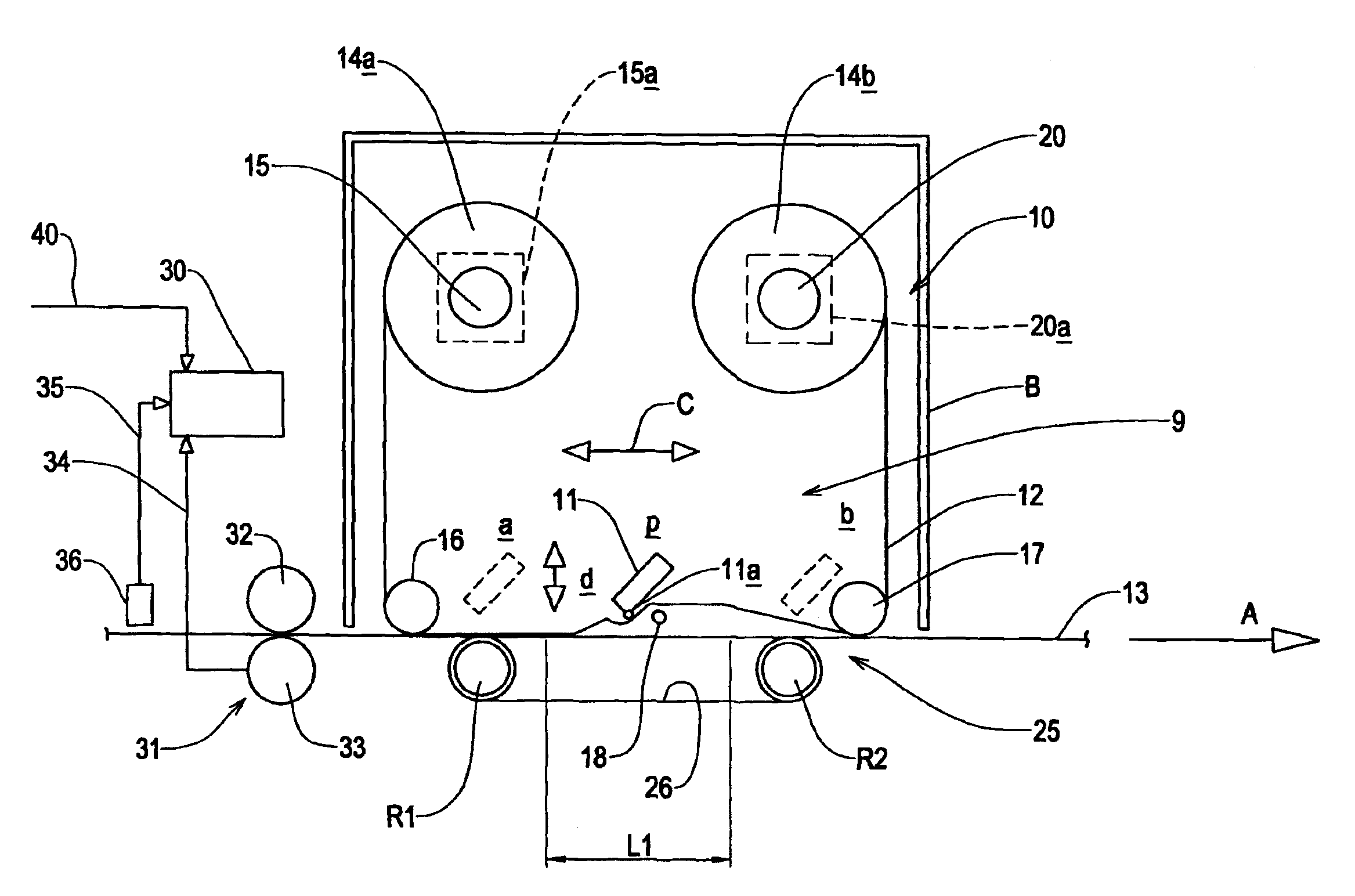
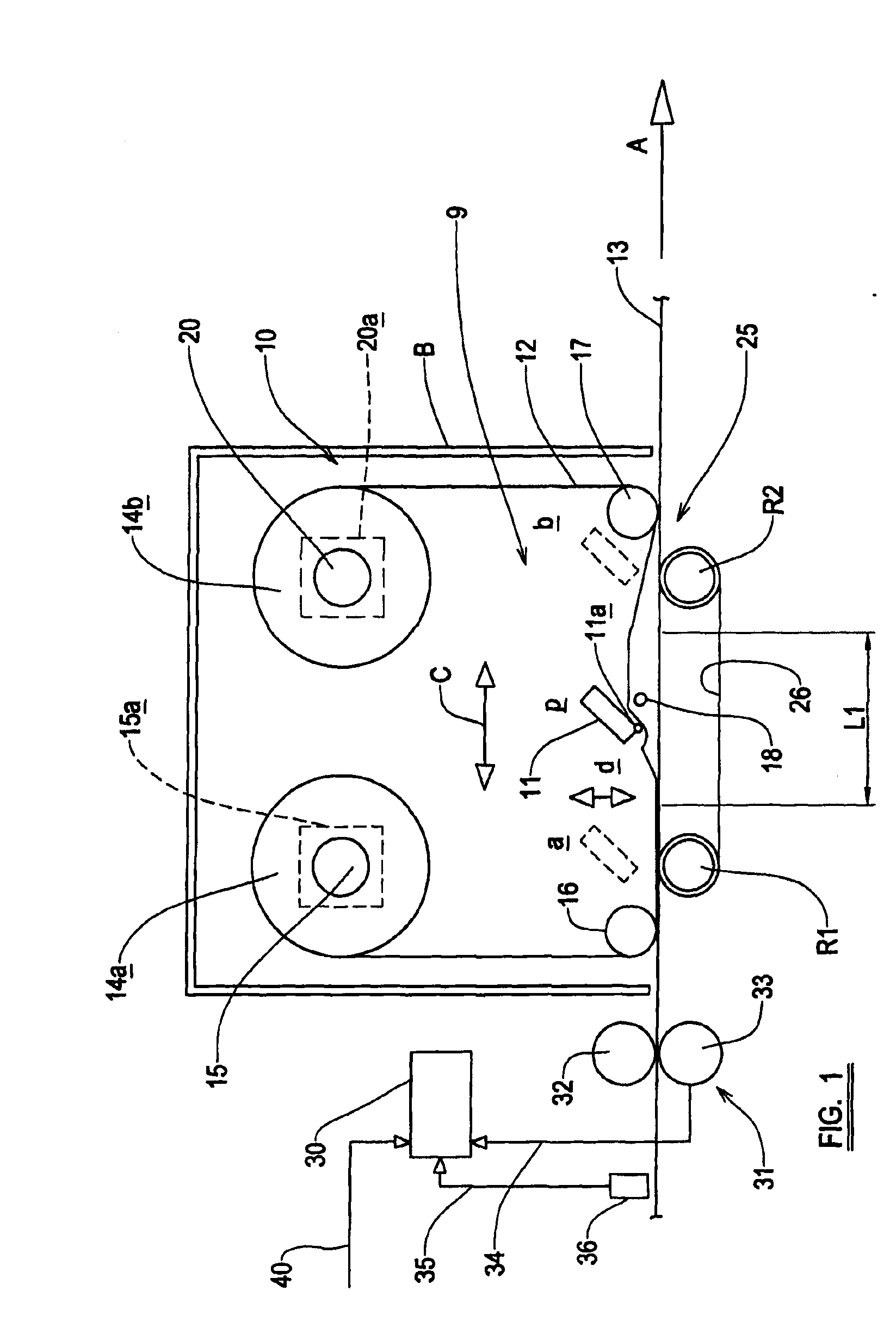
[0021] Referring to the drawing there is shown a printing apparatus 10 including a base B and a printing station 9, at which printing station 9 there is provided a print head 11 which has a plurality of individually energisable thermal printing elements, preferably provided in an array at an edge 11a of the print head 11. The print head 11 is movable relative to a ribbon 12 which carries print medium including ink, whilst the thermal printing elements of the print head 11 are individually selectively energised under computer control, wherein the elements will become hot thus to cause pixels of ink to be removed from the ribbon 12 and deposited onto a substrate 13 which in the arrangement shown in the drawings with the printing apparatus 10 in the orientation shown, is generally below the print head 11.

[0022] The substrate 13 is in this example a continuous flexible packaging web which is subsequently used to package an article or is applied to an article, but may be other packaging...


PUM


Abstract

A method of printing utilising a printing apparatus having a base, a printing station where a print head is mounted, the print head including a plurality of printing elements which are selectively energisable to generate an image on a substrate upon there being relative movement between the substrate and the print head, the print head being moveable relative to the base, and the apparatus including a sensor device to sense the speed of the substrate as the substrate moves relative to the base adjacent to the printing station, and a controller to receive input signals from the sensor device and to control print head movement relative to the base to achieve a desired relative speed between the print head and the substrate, and wherein the method includes predicting when the speed of the substrate relative to the base, as the substrate advances, will be less than a predetermined speed, and in response, moving the print head at the printing station to a downstream extreme position of print head travel, and during printing of an image, moving the print head from the downstream extreme position towards the upstream extreme position.

Description

RELATED APPLICATION [0001] Under 35 U.S.C. §119, this application claims the benefit of a foreign priority application filed in United Kingdom, serial number 0506942.2, filed Apr. 6, 2005. BACKGROUND TO THE INVENTION [0002] This invention relates to a method of printing, and more particularly but not exclusively to a method of thermal printing. [0003] In a thermal printing apparatus, relative movement is required between a substrate and a print head whilst pixels of marking medium are removed from a ribbon, as printing elements of the thermal print head are selectively energised under computer control, to generate a desired image on the substrate. [0004] In one known apparatus, the substrate is intermittently stationary at a printing station, whilst the print head is traversed along the substrate and the printing elements are selectively energised to generate the image. In another apparatus, the print head is held stationary at the printing station whilst the substrate is continuous...

Claims


Application Information

Patent Timeline
Patent Type & Authority Applications(United States)
IPC IPC(8): B41J23/00B41J2/325B41J3/28B41J11/00B41J11/42B41J17/12
CPCB41J2/325B41J17/12B41J11/007B41J3/28
Inventor STARKEY, SIMON
Owner MARKEM IMAJE IND
Why Eureka
Try Eureka