Compound curved concentrator based illuminator

a concentrator and concentrator technology, applied in the field of compound curved concentrator based illuminator, can solve the problems of large volume, high maintenance cost, and difficulty in preventing all light rays from escaping into the environmen

Inactive Publication Date: 2006-10-12
XEROX CORP
View PDF25 Cites 71 Cited by
  • Summary
  • Abstract
  • Description
  • Claims
  • Application Information

AI Technical Summary

Problems solved by technology

Although such illumination systems may be adequate for general use, they are spacious and costly to maintain.
It is usually difficult to prevent all light rays from escaping into the environment.

Method used


Image

  • Compound curved concentrator based illuminator
  • Compound curved concentrator based illuminator
  • Compound curved concentrator based illuminator

Examples


Embodiment Construction

[0018] In embodiments there is illustrated:

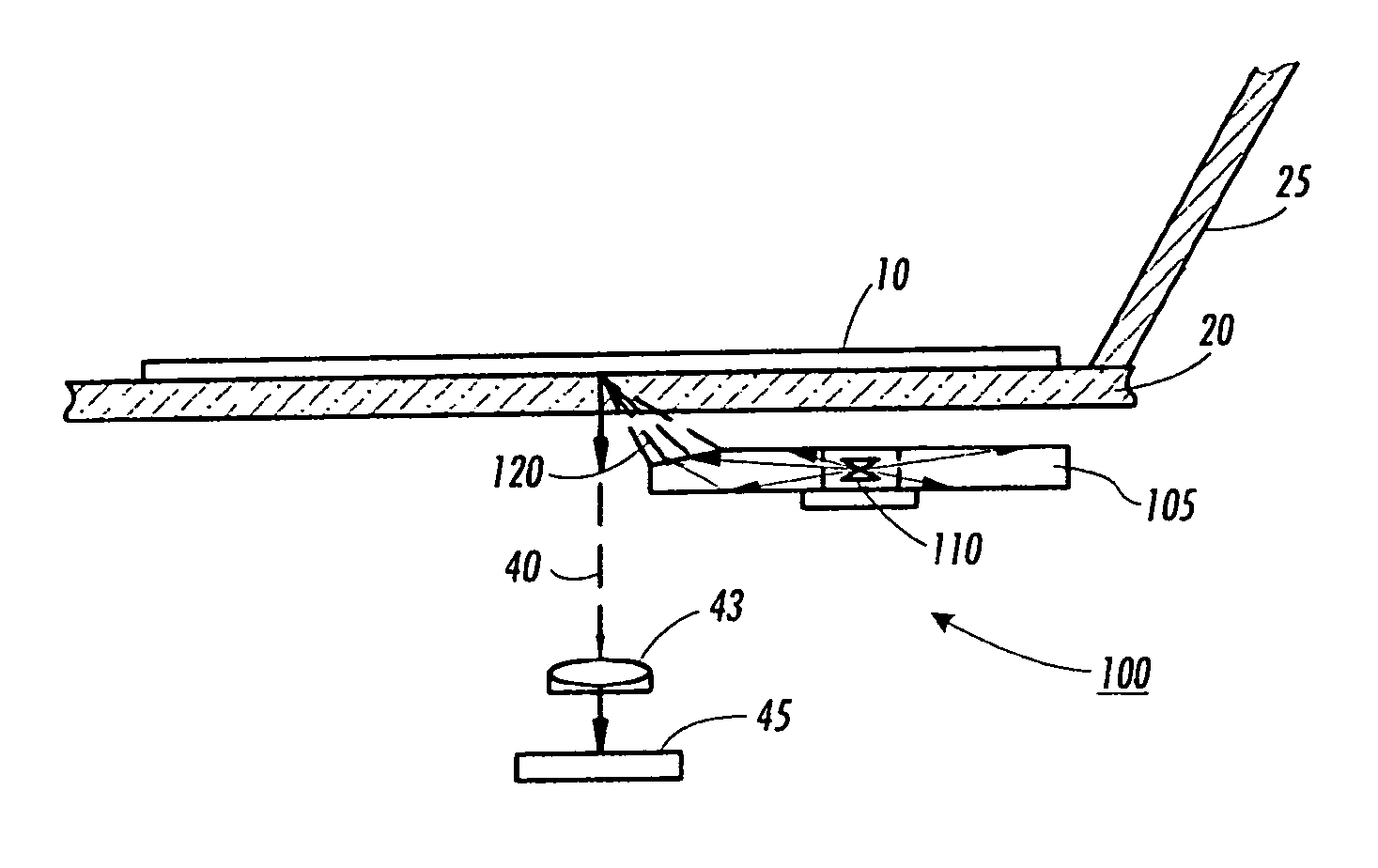
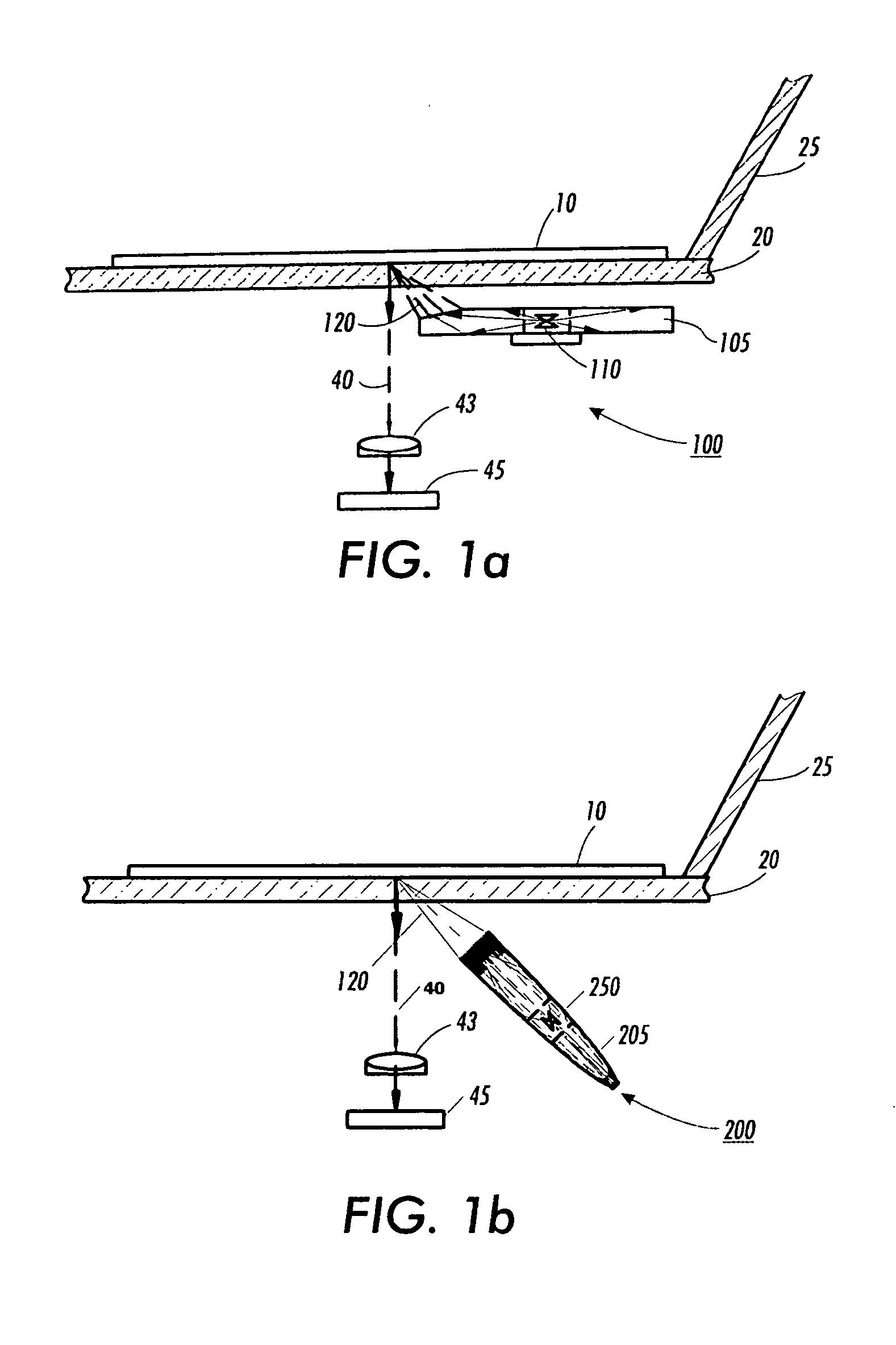
[0019] a light-transmissive element having curved walls to serve as a light guide with an embedded light source. In one embodiment, the curve is parabolic in shape.

[0020]FIG. 1b shows the replacement of the straight-walled light-transmissive element of FIG. 1a with an embodiment of a document illuminator 200 having an light-transmissive element with nonlinear walls 205 in the shape of a compound curved concentrator.

[0021]FIG. 3a shows an enlarged side view of light-transmissive element 200 that serves as a light guide, or an optical connector, in guiding, or connecting, the light rays emanating from light source 250 to a document to be scanned on a platen (not shown). The light source comprises a side emitting LED 230 fitted inside a cavity 240 formed in the light guide 205. Light emanating from the light source is coupled into the light guide through the walls of the cavity. An aperture 260 is formed in the light guide to receive light ...


PUM


Abstract

A document illuminator comprising a light-transmissive element having nonlinear walls. The walls are shaped in the form of a compound parabolic concentrator with an optically inverted configuration. A diffusive optical source receives light from a side emitting LED embedded therein and redirects it to an aperture along with other light rays that go through total internal reflection from the nonlinear walls. The reflected light rays that are collected at the aperture are in turn transmitted at high power and uniform luminescence to illuminate a document for scanning.

Description

BACKGROUND [0001] All references cited in this specification, and their references, are incorporated by reference herein where appropriate for teachings of additional or alternative details, features and / or technical background. [0002] Disclosed in the embodiments herein is a document illuminator comprising a light-transmissive element having a compound curved concentrator profile, such as a compound parabolic concentrator profile. [0003] Document illuminators are generally used in systems for scanning documents. The illumination source typically includes a tungsten lamp or fluorescent lamp and an opposing reflector as described in U.S. Pat. No. 6,236,470 which is incorporated in its entirety by reference herein. Although such illumination systems may be adequate for general use, they are spacious and costly to maintain. [0004] An improved illumination source is provided in a related application, U.S. patent application Ser. No. 10 / 995,462 filed on 23 Nov. 2004, wherein a document i...

Claims


Application Information

Patent Timeline
Patent Type & Authority Applications(United States)
IPC IPC(8): H04N1/46
CPCH04N1/02815H04N1/40056H04N1/0284
Inventor HERLOSKI, ROBERT
Owner XEROX CORP
Why Eureka
Try Eureka