Image forming apparatus and method

a technology of image forming apparatus and forming apparatus, which is applied in the direction of electrographic process apparatus, instruments, optics, etc., can solve the problems of increasing the burden of users and increasing the waste of recording paper, and achieve the effect of preventing paper jamming and easy paper decision

Inactive Publication Date: 2006-10-12
CANON KK
View PDF1 Cites 16 Cited by
  • Summary
  • Abstract
  • Description
  • Claims
  • Application Information

AI Technical Summary

Benefits of technology

[0008] Another object of the present invention is to provide an image forming apparatus and control method capable of preventing the waste of the recording paper and facilitating handling of the recording paper after the image formation.
[0011] According to the present invention, the image forming apparatus carries out the control in such a manner that when the image formation is not performed normally on the first side of the recording paper during the alternate duplex printing, the recording paper is conveyed to the reversing section. Thus the conveyance of the recording paper is continued as in the normal image formation, but the image formation onto the second side is not performed. In this way, the sequence of the recording paper ejected to the paper output section is the same as in the normal printing, but the image formation is not performed on the second side of the recording paper that does not undergo the normal image formation. As a result, a user can easily decide the paper on which the image formation is not performed normally. In addition, if it is found that a paper that likely causes a paper jam is being conveyed on the conveying path, ejecting the paper to the paper output section without adding any operation can prevent the paper jam. Thus, the subsequent recording papers being conveyed through the apparatus can undergo normal printing and ejection.

Problems solved by technology

According to the patent document, however, if the size of the paper being conveyed through the machine does not agree with the user-designated paper size, the following problems can occur during the printing.
More specifically, since the recording paper that is waiting for the back side printing on the conveying path in the reversing section (that is, the recording paper that can be printed normally) is also ejected to the outside, reprinting must be made for all the number of papers being carried through the machine at the same time, thereby increasing a waste of the recording paper.
Thus, the user must search for the sheet on which the image formation is not made normally to remove it, which will result in an increase in the burden of the user.

Method used


Image

  • Image forming apparatus and method
  • Image forming apparatus and method
  • Image forming apparatus and method

Examples


embodiment 1

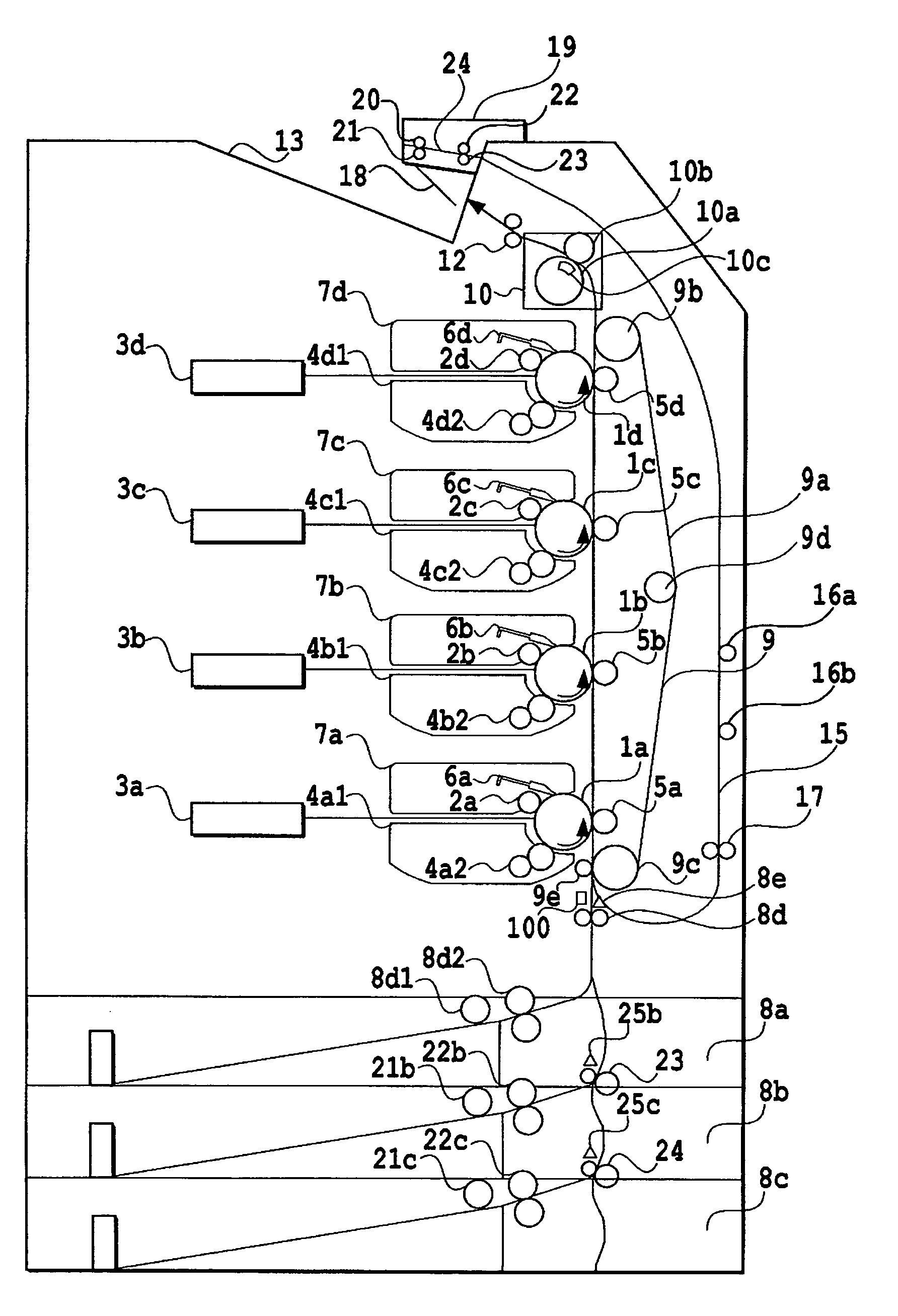
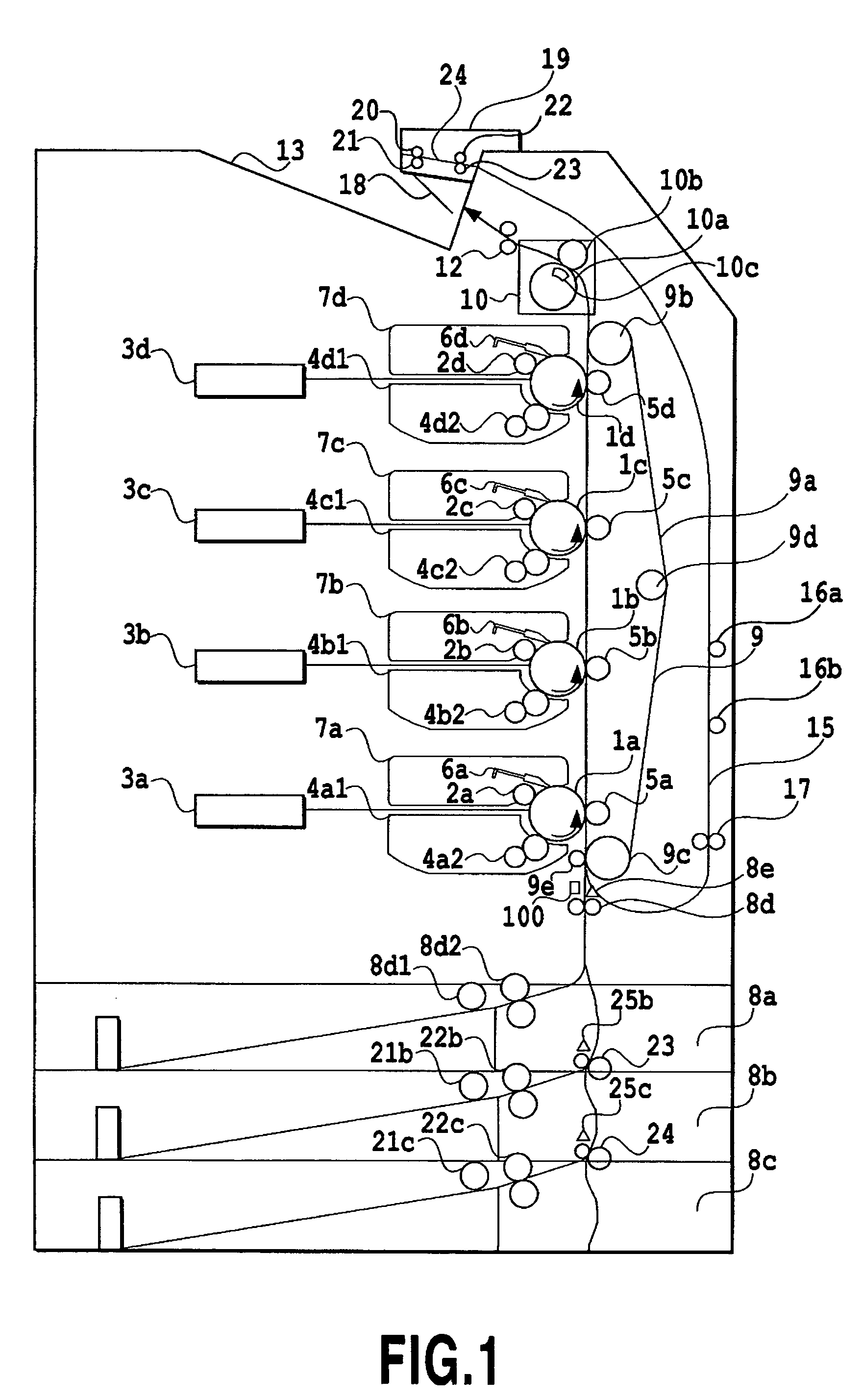
[0022]FIG. 1 is a diagram showing an overall configuration of an image forming apparatus of the present embodiment. The present embodiment employs as an image forming apparatus a color laser printer capable of forming multiple colors. First, the overall configuration of the image forming apparatus will be described, followed by the description of various portions.

(Overall Configuration)

[0023] The image forming apparatus as shown in FIG. 1 includes four photoconductive drums 1 (1a-1d) as image carriers. The photoconductive drums 1 each have the following components around them in the direction of rotation in the order described below, thereby constituting an image forming means. A charging means 2 (2a-2d) for uniformly charging the surface of the photoconductive drum 1. An exposure means 3 (3a-3d) for applying a laser beam in response to image information to generate an electrostatic latent image on the photoconductive drum 1. A developing means 4 (4a-4d) for depositing toner on t...

embodiment 2

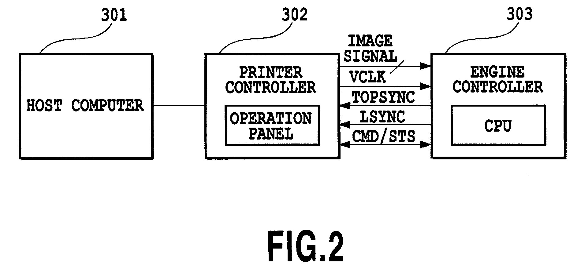
[0062] As the first embodiment, the second embodiment is also applied to the image forming apparatus with the configuration as shown in FIGS. 1 and 2. Accordingly, the description about the contents already described in the explanation of the first embodiment will be omitted in the second embodiment, and the same components in the diagrams are designated by the same reference numerals.

(When Image Formation Fault Occurs Because of Disagreement of Paper Type)

[0063]FIG. 7 illustrates a paper conveyance sequence in a case where an image formation fault occurs because of the paper type disagreement of the paper during alternate duplex printing. Numbers in FIG. 7 indicate the order of the sheets.

[0064] In the present embodiment, it is assumed that the print signal fed from the printer controller 302 is the same as that of the embodiment 1 which is shown in FIG. 4, and that as for the papers fed, two plain papers are fed continuously, followed by a third paper, a transparent paper, whi...


PUM


Abstract

The length of recording paper being conveyed to an image forming section is detected. If it is found that the length is shorter as a result of the detection, the recording paper is conveyed to a reversing section to be refed to the image forming section to continue conveyance of the recording paper as in the normal image formation, but without performing the image formation. As a result, the sequence of the recording paper ejected to the paper output section is the same as that of normal printing. Thus a user can easily decide the paper on which the image formation is not carried out normally.

Description

BACKGROUND OF THE INVENTION [0001] 1. Field of the Invention [0002] The present invention relates to an image forming apparatus such as a copying machine and laser printer and an image forming method. [0003] 2. Description of the Related Art [0004] An image forming apparatus such as a copying machine and laser printer generally feeds and conveys recording paper from a paper feeder to an image forming section, carries out image formation by a transfer method (indirect method) or direct method, and ejects the recording paper passing through the image formation to the paper output section. Among such image forming apparatuses, there are those which automatically perform image formation on both sides of the recording paper in response to a duplex printing instruction of the recording paper, and output the recording paper passing through the image formation. [0005] Such an image forming apparatus that carries out the image formation on both sides of the recording paper is disclosed in Ja...

Claims


Application Information

Patent Timeline
Patent Type & Authority Applications(United States)
IPC IPC(8): G03G15/00
CPCG03G2215/00734G03G15/234
Inventor NIHEI, HIRONOBU
Owner CANON KK
Why Eureka
Try Eureka