
Self-drilling screw for use with steel sheets

Inactive Publication Date: 2006-10-12
SHINJO MFG CO LTD
View PDF7 Cites 14 Cited by
  • Summary
  • Abstract
  • Description
  • Claims
  • Application Information

AI Technical Summary

Benefits of technology

[0013] In use, a driving tool will be engaged with the drive head so as to rotate the threaded shank, causing the piercing portion at the free end thereof to punch a relatively small hole in a steel sheet. As a result, the conical portion of said shank will expand the rim of this small hole into a funnel-shape in the burring manner. Thus, the thread of the shank will be forced into engagement with such an expanded rim of the hole, to thereby affording a firm retention of this screw. If the flank angle of the thread facing the driven head is considerably sharpened to be about 10° or less (as compared with the usual angle of 30°), then the retention will be enhanced further.
[0014] As the driven head is forcibly rotated to fasten any attachment to the steel sheet, its torque will reach a prescribed limit of tightening torque so as to break the junction. Thus, any excessive torque will no longer be imparted to the steel sheet around the hole, thereby protecting it from breakage and ensuring a firm retention of the screw therein. The prescribed limited torque may easily be adjusted by changing the dimension, that is diameter and height, of the weld lug.
[0017] It is easy for the junction of drive head to have a reliable and unvaried breaking torque. For this purpose, the size of semispherical weld lug disposed either at the top center of driven head or on the thin stud bottom may be adjusted. Alternatively, the molten volume of conical weld lug formed on said stud bottom may be adjusted.
[0018] A newly exposed surface of the broken junction is much smaller than the driven head, and a zinc plating covering the driven head is ready to undergo a sacrificial anodic oxidation so as to protect such a small exposed surface. Thus, the broken junction will never impair the appearance of the screw head fixed on the steel sheet.

Problems solved by technology

A female thread that will be formed by any conventional self-drilling screw through such a thin and single steel sheet is inevitably of a poor strength insufficient to fix the attachments or the like.
Any unskilled operations of a worker, his or her incorrect choice or improper adjustment of an electric driving tool for use are likely to cause an excessively strong tightening torque.
Consequently, many troubles have occurred such that the female-threaded holes would be broken disabling the fixing of such attachments.
However, this proposal on the self-drilling screw and the advanced manner of its fixing has not proved satisfactory.
Any worker's unskilled operations, incorrect choice of electric tool or improper torque adjustment thereof do cause troubles, such that an excessively strong tightening torque would bring about breakage of the female-threaded holes.

Method used


Image

  • Self-drilling screw for use with steel sheets
  • Self-drilling screw for use with steel sheets
  • Self-drilling screw for use with steel sheets

Examples


Embodiment Construction

[0028] Now some embodiments of the present invention will be described referring to the accompanying drawings.

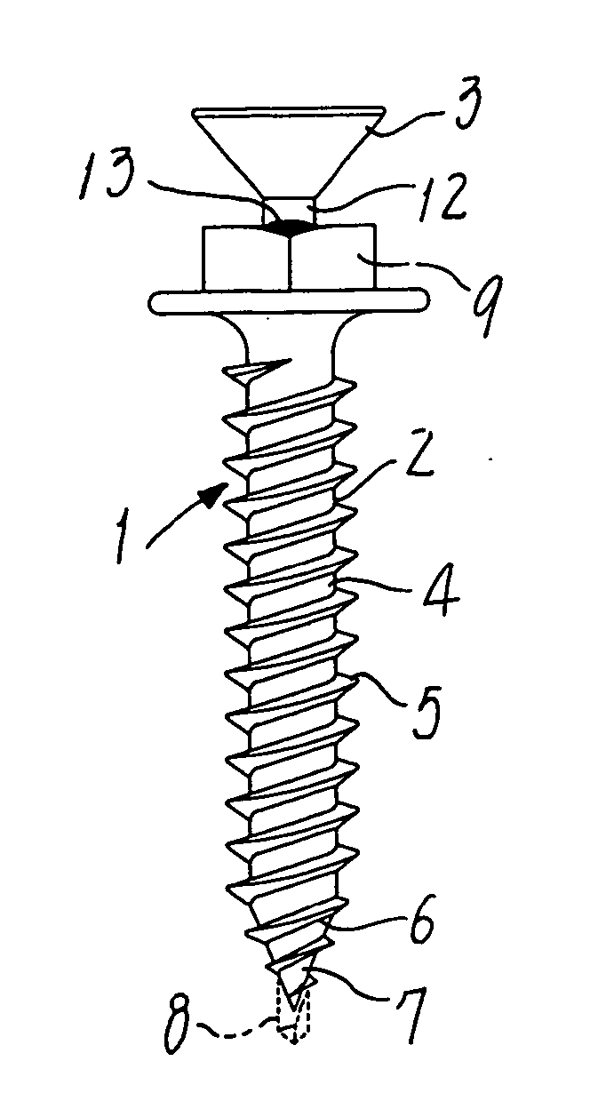
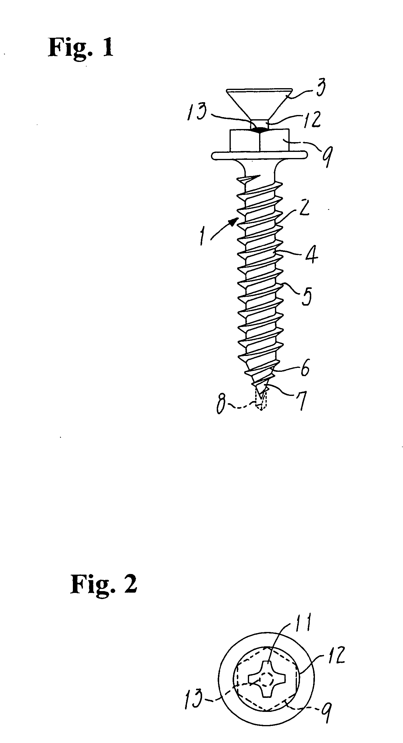
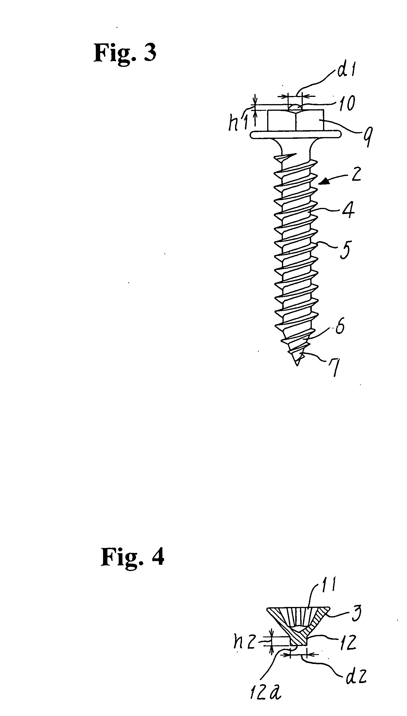
[0029]FIGS. 1 and 2 show a self-drilling screw in its entirety for use with thin steel sheets. This screw 1 is composed of a main body 2 shown in FIG. 3 and a drive head 3 shown in FIG. 4 and resistance welded to the main body 2.

[0030] A threaded shank 4 of the screw main body 2 is composed of a parallel portion 5 and a conical portion 6 continuing therefrom. The main body 2 further comprises a drill bit 7 as the piercing portion, but as indicated by the phantom lines in FIG. 1 a thin drill 8 may substitute for the drill bit 7. Formed at the other end of threaded shank 4 is a driven head 9 with a weld lug 10 of a prescribed size and protruding from the top center of this head. The weld lug is of a semispherical shape having a prescribed diameter ‘d1’ and height ‘h1’ such as to define a breaking torque withstanding the boring and screwing action of main body 2. The screw ma...


PUM


Abstract

The main body (2) of a self-drilling screw has a driven head (9) having at its top central region a weld lug (10) of a prescribed size. The screw also has a discrete drive head (3) having in its top a hole (11) for engagement with a driving tool. A thinned stud (12) continuing from the drive head (3) is resistance welded to the top center of driven head (9), using the weld lug (10) to form between these heads a torque-limiting junction (13) ready to break at a prescribed torque. As the main body (2) of the screw for use with thin steel sheets is tightened, the drive head (3) will be removed due to breakage of the junction (13). Any excessive tightening torque imparted to the screw will not break a female-threaded hole formed in the steel sheet, but firmly retaining the screw on it.

Description

FIELD OF THE INVENTION [0001] The present invention relates to a self-drilling screw adapted for use to secure any articles, fittings or the like to a steel sheet that serves as the support for said article and has a thickness of about 1.0 mm or less. BACKGROUND ART [0002] Self-drilling screws can automatically be fastened through any metal sheets simultaneously with the drilling of holes through said sheets. Certain colored and corrugated steel sheets used as the roofs and / or walls in considerably large buildings can conveniently be fixed in position by using a number of such self-drilling screws. Those thin colored steel sheets are in usual cases merely about 1.0 mm thick, and in other cases still thinner for example to be 0.7 mm thick. [0003] There has been a strong demand for the technique such that any necessary attachments or the like be fixed to thin steel sheets with use of self-drilling screws. Such screws should penetrate the steel sheet through holes preliminarily formed ...

Claims


Application Information

Patent Timeline
IPC IPC(8): F16B31/00
CPCF16B25/0021F16B31/021F16B25/0047
Inventor SHINJO, KATSUMI
Owner SHINJO MFG CO LTD
Learn More