Diagnostic and prognostic method and system

a diagnostic and prognostic technology, applied in the field of mathematical model based diagnostic and prognostic systems, can solve the problems of large computational time and failure to identify particular causes of failures

Active Publication Date: 2006-10-12
CATERPILLAR INC
View PDF21 Cites 64 Cited by
  • Summary
  • Abstract
  • Description
  • Claims
  • Application Information

AI Technical Summary

Benefits of technology

[0005] One aspect of the present disclosure includes a method for diagnosing a system. The method may include obtaining a plurality of input parameters from the system. The system may generate actual values of one or more output parameters based on the plurality of input parameters. The method may also include independently deriving values of the one or more output parameters, based on the plurality of input parameters, using a computational model, and detecting a divergence between the derived values and the actual values. Further, the method may include identifying respective desired statistic distributions of the plurality of input parameters, based on the actual values of the one or more output parameters, using the computational model.
[0006] Another aspect of the present disclosure includes a method for providing a prognosis associated with a system. The method may include obtaining a plurality of input parameters from the system. The system under diagnose may generate actual values of one or more output parameters based on the plurality of input parameters. The method may also include independently deriving values of the one or more output parameters using a computational model based on the plurality of input parameters, and estimating future values of the one or more output parameters of the system by calculating a trend of differences between the actual values and the derived values. Further, the method may include detecting a potential divergence between the future values and the derived values, and identifying respective desired statistic distributions of the plurality of input parameters using the computational model based on the future values of the one or more output parameters.
[0007] Another aspect of the present disclosure includes a diagnostic and prognostic system. The diagnostic and prognostic system may include a plurality of input elements configured to accept a respective plurality of input parameters from a system being diagnosed, and one or more output elements configured to accept respective one or more output parameters. The diagnostic and prognostic system may also include a processor. The processor may be configured to diagnose and predict a failure associated with any of the plurality of input parameters based on a diagnostic model. The diagnostic model may be created by obtaining data records associating the plurality of input parameters and the one or more output parameters, and generating a computational model indicative of interrelationships between the plurality of input parameters and the one or more output parameters based on the data records. The model may be created further by determining original desired respective statistical distributions of the plurality of input parameters of the computational model based on a zeta statistic of the computational model.
[0008] Another aspect of the present disclosure includes a work machine. The work machine may include an engine and an electronic control module configured to control operation of the engine by using actual values of one or more output parameters based on a plurality of input parameters. The work machine may also include a diagnostic and prognostic system. The diagnostic and prognostic system may include a processor, which may be configured to obtain the plurality of input parameters and derive values of the one or more output parameters based on the plurality of input parameters using a computational model indicative of interrelationships between the plurality of input parameters and the one or more output parameters. The processor may be further configured to identify a potential failure associated with any of the plurality of input parameters based on a zeta statistic of the computational model.

Problems solved by technology

Some of these conventional techniques operate only to classify operation conditions into two categories, normal or abnormal, without offering further analysis to identify possible causes for failures.
However, such techniques may require a large amount of computational time and may fail to identify particular causes of failures, such as failures associated with particular inputs and their control logics.

Method used


Image

  • Diagnostic and prognostic method and system
  • Diagnostic and prognostic method and system
  • Diagnostic and prognostic method and system

Examples


Embodiment Construction

[0015] Reference will now be made in detail to exemplary embodiments, which are illustrated in the accompanying drawings. Wherever possible, the same reference numbers will be used throughout the drawings to refer to the same or like parts.

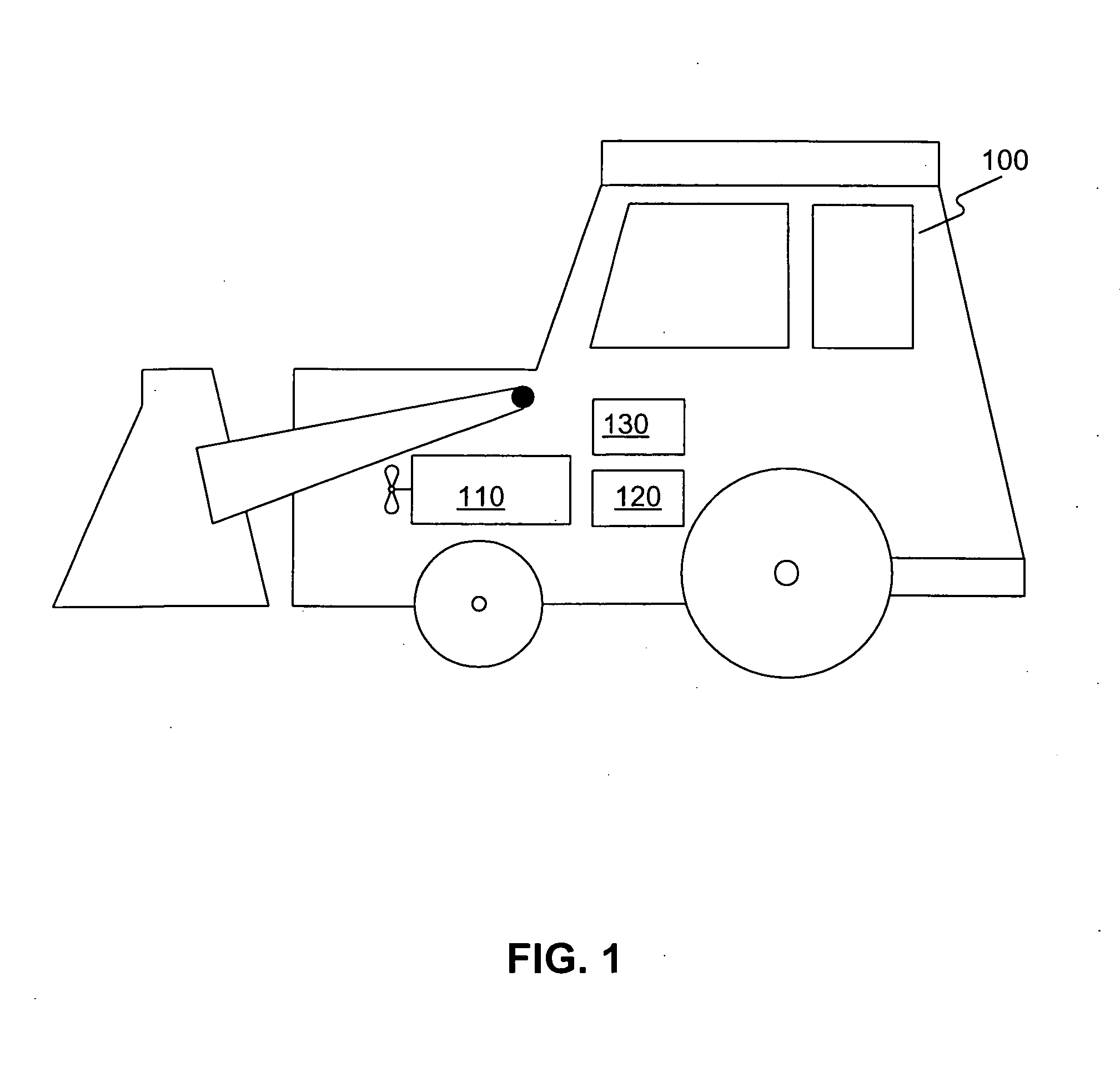
[0016]FIG. 1 illustrates an exemplary work machine 100 in which features and principles consistent with certain disclosed embodiments may be incorporated. Work machine 100 may refer to any type of fixed or mobile machine that performs some type of operation associated with a particular industry, such as mining, construction, farming, transportation, etc. and operates between or within work environments (e.g., construction sites, mining sites, power plants and generators, roadways, etc.). Non-limiting examples of mobile machines include commercial machines, such as trucks, cranes, earth moving vehicles, mining vehicles, backhoes, material handling equipment, farming equipment, marine vessels, aircraft, power generators, manufacturing machinery, an...


PUM


Abstract

A method for diagnosing a system is provided. The method may include obtaining a plurality of input parameters from the system. The system may generate actual values of one or more output parameters based on the plurality of input parameters. The method may also include independently deriving values of the one or more output parameters, based on the plurality of input parameters, using a computational model, and detecting a divergence between the derived values and the actual values. Further, the method may include identifying respective desired statistic distributions of the plurality of input parameters, based on the actual values of the one or more output parameters, using the computational model.

Description

TECHNICAL FIELD [0001] This disclosure relates generally to diagnostic and prognostic systems and, more particularly, to mathematical model based diagnostic and prognostic systems. BACKGROUND [0002] Modern work machines often are equipped with complex control systems to support a wide range of operations. The operational conditions of these complex systems, such as an engine control system, may need to be monitored in order to diagnose and / or predict certain failures of the systems. A wide variety of techniques and apparatus have been developed for diagnosing engines and engine control systems, including expert systems, fuzzy logic based systems, and neural network models. These techniques and apparatus may be used for diagnostic and / or prognostic purposes. A diagnostic system may be used to identify a root source of a failure after the failure has occurred, and a prognostic system may be used to identify a root source of a failure before the failure has occurred. [0003] Some of the...

Claims


Application Information

Patent Timeline
Patent Type & Authority Applications(United States)
IPC IPC(8): G06F11/00
CPCG07C5/0808G05B23/0254
Inventor GRICHNIK, ANTHONY J.SESKIN, MICHAELWILLDEN, WADE
Owner CATERPILLAR INC
Why Eureka
Try Eureka