
Sliding rail assembly for a sliding panel movable along a track

a sliding panel and track technology, applied in the direction of door/window fittings, multi-purpose tools, construction, etc., can solve the problems of plastic material having the tendency to wear, rollers being dislodged from the track, and the assembly becomes difficult to move across the opening, so as to reduce the complexity

Active Publication Date: 2006-10-19
QUANEX HOMESHIELD LLC
View PDF41 Cites 28 Cited by
  • Summary
  • Abstract
  • Description
  • Claims
  • Application Information

AI Technical Summary

Benefits of technology

"The present invention is a sliding rail assembly for a sliding panel movable along a track between open and closed positions. The assembly includes a runner and a glide with a layer of polymeric material to facilitate smooth sliding movement of the glide along the runner. The use of the adhesive allows the polymeric material to bond to the interior surface of the glide and the runner, providing good wear resistance between them. The sliding movement of the glide eliminates the need for rollers to support the load of the panel, which reduces the number of moving parts in the assembly. Additionally, the glide is adapted to extend from the sliding panel and presents a C-shaped cross-section which allows it to surround the track and act as a guide for the panel."

Problems solved by technology

When the rollers are not in alignment with the guide ridges of the tracks, such as when the panel becomes warped or the tracks are out of alignment with respect to each other, which is a common result of poor installation or a subsequent accident dislodging the assembly, the assembly becomes difficult to move across the opening, i.e., binds, or the rollers become dislodged from the track.
The plastic material will have the tendency to wear.
However, because the glide is formed entirely from the plastic material which is designed to flex, the glide limits the weight of the panel to which it may be attached in order for the track to support the load from the glide and the panel.

Method used


Image

  • Sliding rail assembly for a sliding panel movable along a track
  • Sliding rail assembly for a sliding panel movable along a track
  • Sliding rail assembly for a sliding panel movable along a track

Examples


Embodiment Construction

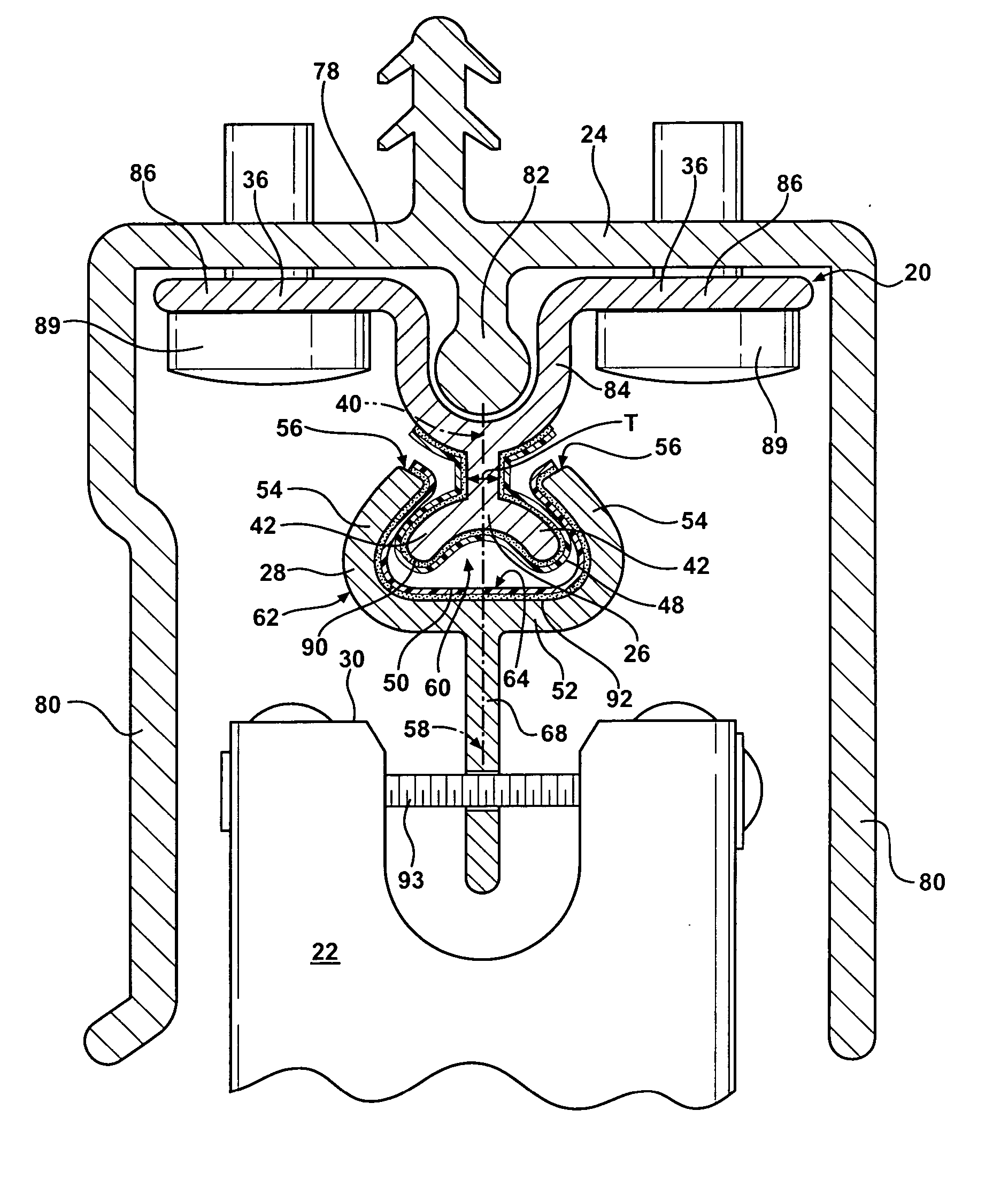
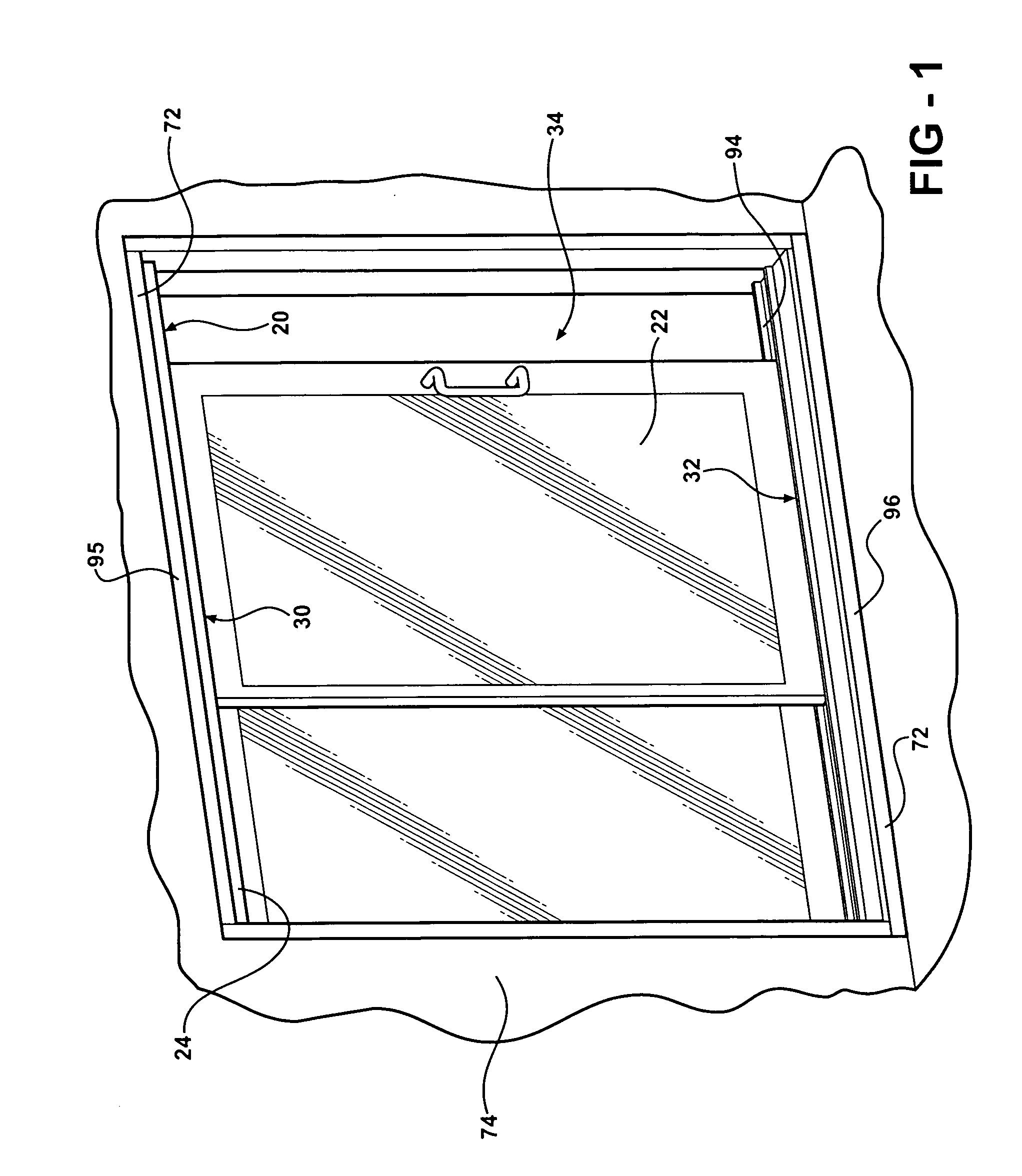
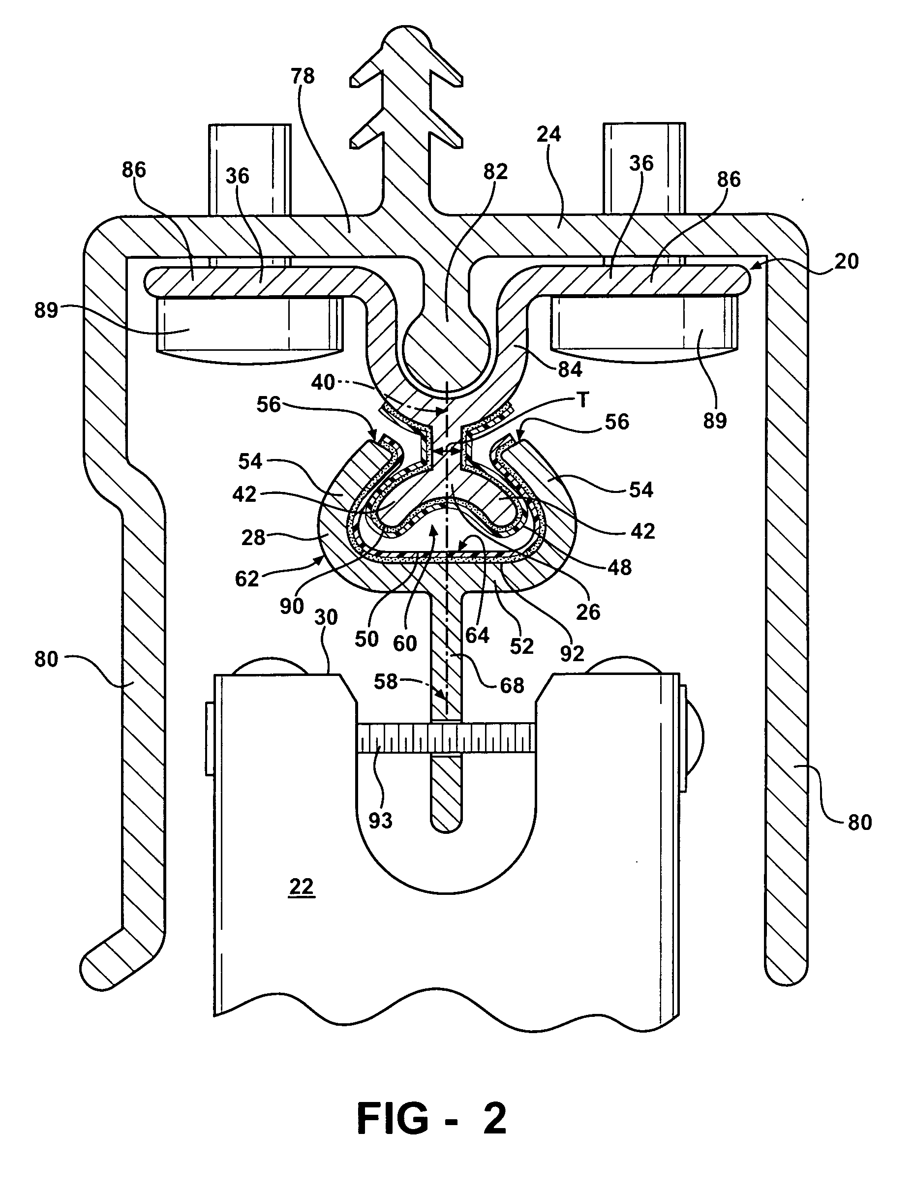
[0030] The present invention relates to a sliding rail assembly 20 for a sliding panel 22 movable along a track 24 between an open and a closed position. The assembly is shown generally at 20 in FIG. 1. The assembly 20 includes a runner 26 adapted to extend from the track 24 and a glide 28 for sliding engagement along the runner 26 and adapted to extend from the sliding panel 22. The sliding panel 22 is a screen door, a glass door, a window, or any other type of panel for covering and uncovering an opening 34.

[0031] Referring again to FIG. 1, a surround 72 defines the opening 34 within a structure 74, such as a wall of a house, and the track 24 is mounted to a top or a bottom of the surround 95, 96. A typical track 24 is shown in FIG. 2, which has a U-shaped cross-section including a bottom 78 and a pair of sides 80 extending perpendicularly from the bottom 78 in spaced and parallel relationship. However, the track 24 is not limited to being shaped as a U-shaped cross-section and i...


PUM


Abstract

A sliding rail assembly (20) for a sliding panel (22), movable along a track (24) between open and closed positions, includes a runner (26) and a glide (28) for sliding engagement along the runner (26). The runner (26) is adapted to extend from the track (24). The glide (28) has an interior surface (64) disposed about the runner (26) and an exterior surface (62) adapted to extend from the sliding panel (22). A layer of polymeric material (48) is secured by an adhesive (90) to either one of the interior surface (64) of the glide (28), the runner (26), or both for facilitating sliding movement of the glide (28) along the runner (26).

Description

CROSS REFERENCE TO RELATED APPLICATION [0001] This application claims the benefit of U.S. provisional patent application Ser. No. 60 / 672,891, filed Apr. 19, 2005.BACKGROUND OF THE INVENTION [0002] 1. Field of the Invention [0003] The invention generally relates to a sliding rail assembly for a sliding panel movable along a track. More specifically, the invention relates to using polymeric material to facilitate sliding movement of the panel along the track. [0004] 2. Description of the Related Art [0005] Traditional assemblies for moving a panel include a surround which defines an opening and a pair of tracks which are disposed on opposite sides of the opening. The panel, such as a window or a door, is attached to the tracks and the panel is moved along the tracks to cover and uncover the opening. In these traditional assemblies, a guide ridge is typically formed along each of the tracks. Rollers are disposed on opposite sides of the panel for rolling the panel along the respective ...

Claims


Application Information

Patent Timeline
Patent Type & Authority Applications(United States)
IPC IPC(8): E05D15/00
CPCE05D15/0647E05D15/0652E05D15/0682E05Y2800/205Y10T16/3543Y10T16/379Y10T16/37Y10T16/353Y10T16/373Y10T16/355E05Y2900/132
Inventor QUINN, DONMARTINEAU, ROBERT C.SAWYERS, JEFF V.
Owner QUANEX HOMESHIELD LLC
Learn More