Plasma display apparatus and method of driving the same

a technology of display apparatus and plasma, which is applied in the direction of instruments, static indicating devices, etc., can solve the problems of deterioration of contrast, reduced driving margin, and difficulty in sufficiently initializing the discharge cells of the pdp, so as to prevent the deterioration of driving margin, improve contrast characteristics, and reduce the address period

Inactive Publication Date: 2006-10-19
LG ELECTRONICS INC
View PDF12 Cites 25 Cited by
  • Summary
  • Abstract
  • Description
  • Claims
  • Application Information

AI Technical Summary

Benefits of technology

[0089] According to the present invention, the magnitude of the reset pulses is larger in the low gray level sub-fields that realize the low gray levels and the magnitude of the reset pulses is smaller in the high gray level sub-fields that realize the high gray levels in one frame so that it is possible to improve the contrast characteristic and to prevent the driving margin from deteriorating.
[0090] According to the present invention, the widths of the scan pulses applied to the plurality of scan electrode groups each comprising one or more scan electrode are controlled in one sub-field in the order of scanning, the widths of the scan pulses in the high gray level sub-fields are increased when the APL is high, and the widths of the scan pulses in the low gray level sub-fields are increased when the APL is low so that it is possible to stabilize the entire discharge of the PDP and to reduce the address period. Therefore, the number of sustain pulses applied in the sustain period is increased so that it is possible to improve the brightness realized when the PDP is driven.

Problems solved by technology

Therefore, the magnitude of the unnecessary discharge that does not contribute to display of an image increases, thereby causing a deterioration in contrast.
However, according to such a driving method, it is difficult to sufficiently initialize the discharge cells of the PDP compared with the conventional driving method in which the reset pulse is applied in the reset periods of all of the sub-fields so that the driving margin is reduced.
As a result, the address discharge becomes unstable when the scan electrode Yn is scanned last.

Method used


Image

  • Plasma display apparatus and method of driving the same
  • Plasma display apparatus and method of driving the same
  • Plasma display apparatus and method of driving the same

Examples


first embodiment

[0222] An embodiment of the method of driving the plasma display apparatus according to the present invention will be described in FIG. 12.

[0223]FIGS. 12A and 12B illustrate the first embodiment of the method of driving the plasma display apparatus for applying the reset pulses according to the present invention.

[0224] As illustrated in FIGS. 12A and 12B, according to the first embodiment of the method of driving the plasma display apparatus comprising the scan electrodes, the sustain electrodes, and the plurality of address electrodes that intersect the scan electrodes and the sustain electrodes, the magnitude of the reset pulses applied to the scan electrodes in the reset periods of low gray level sub-fields among the sub-fields of one frame is larger than the magnitude of the reset pulses applied to the scan electrodes in the reset periods of the remaining sub-fields.

[0225] For example, as illustrated in FIG. 12A, when one frame comprises eight sub-fields, the magnitude V2 of ...

second embodiment

[0248] According to the first embodiment of the method of driving the plasma display apparatus, the magnitude of the reset pulses is controlled in the low gray level sub-fields among the sub-fields in one frame. However, the magnitude of the reset pulses may also be controlled in the high gray level sub-fields among the sub-fields in one frame, which will be described with reference to a second embodiment of the method of driving the plasma display apparatus for applying the reset pulses according to the present invention.

[0249]FIGS. 16A and 16B illustrates the second embodiment of the method of driving the plasma display apparatus for applying the reset pulses according to the present invention.

[0250] As illustrated in FIGS. 16A and 16B, according to the second embodiment of the method of driving the plasma display apparatus comprising the scan electrodes, the sustain electrodes, and the plurality of address electrodes that intersect the scan electrodes and the sustain electrodes...

third embodiment

[0273] As described above, the magnitude of the reset pulses applied to the scan electrodes in the reset periods of the sub-fields comprised in one frame is controlled in the low gray level sub-fields or in the high gray level sub-fields. However, unlike the above, the reset pulses of the sub-fields comprised in one frame may be determined to have three or more different voltage values. Such a driving method will be described with reference to the third embodiment of the method of driving the plasma display apparatus for applying the reset pulses according to the present invention.

[0274]FIGS. 20A and 20B illustrate the third embodiment of the method of driving the plasma display apparatus for applying the reset pulses according to the present invention.

[0275] As illustrated in FIGS. 20A and 20B, according to the third embodiment of the method of driving the plasma display apparatus comprising scan electrodes, sustain electrodes, and a plurality of address electrodes that intersect...


PUM


Abstract

A plasma display apparatus and a method of driving the same, more particularly to, a plasma display apparatus considering the gray level values of sub-fields and a method of driving the same are provided. The plasma display apparatus controls the magnitudes of reset pulses or the widths of scan pulses in units of sub-fields thereby improving contrast, preventing driving margins from deteriorating, stabilizing discharges and improving. brightness.

Description

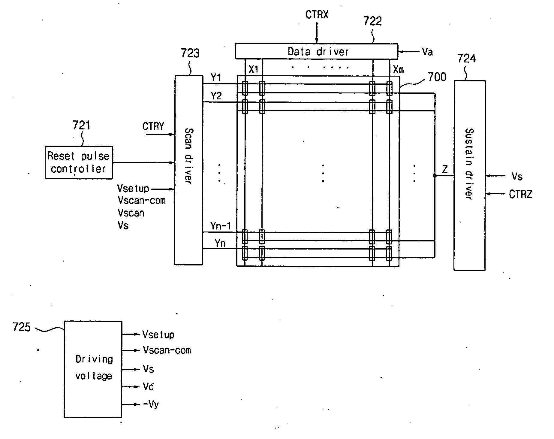
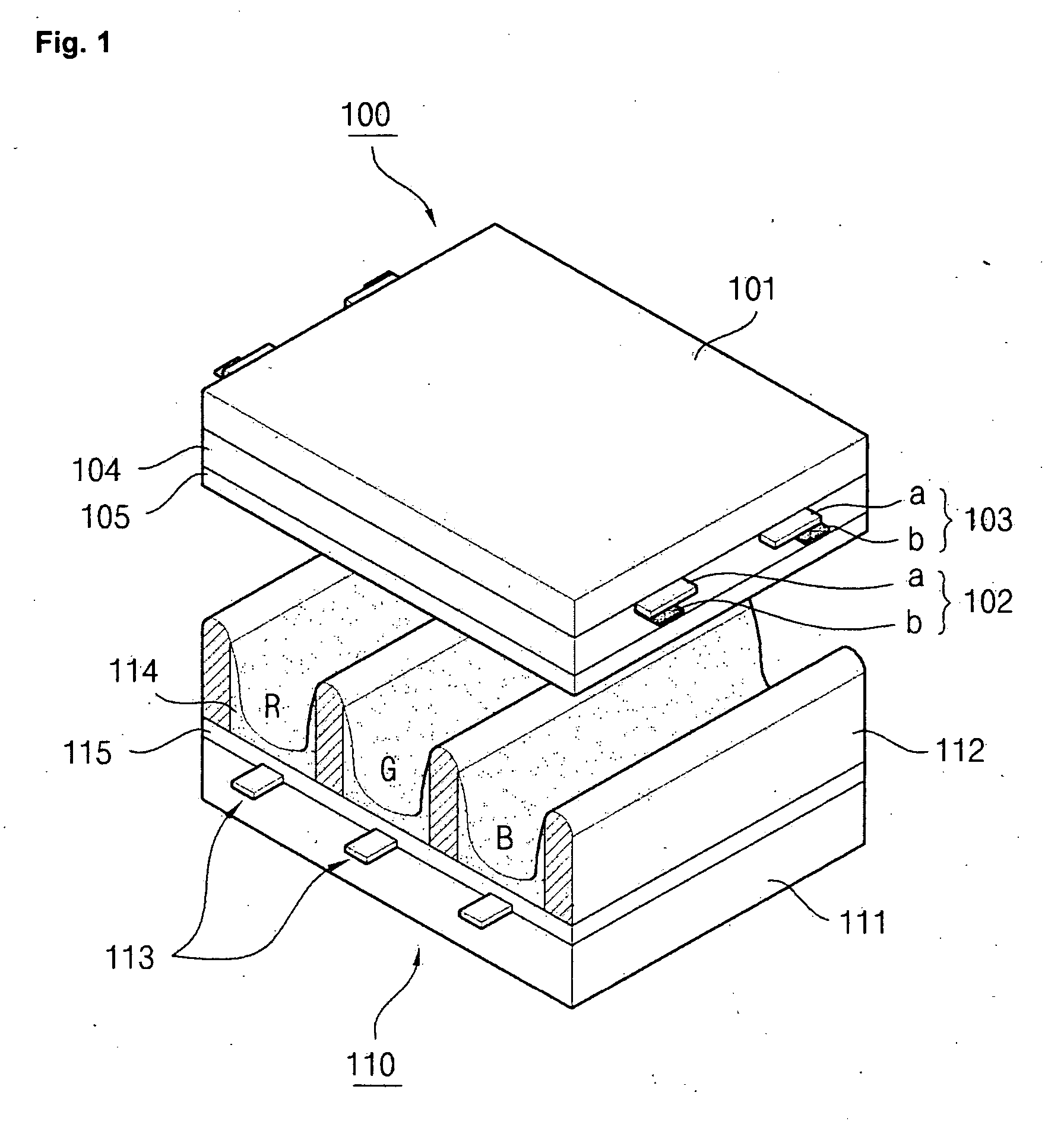
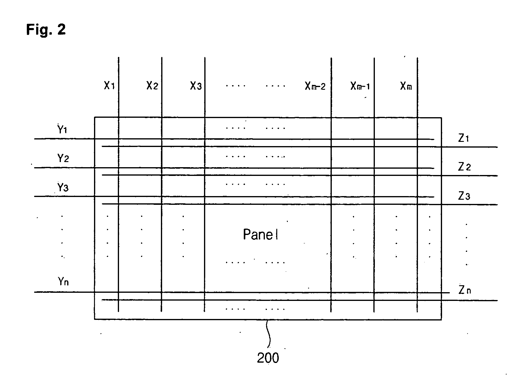
[0001] This nonprovisional application claims priority under 35 U.S.C. §119(a) on patent application Nos. 10-2005-031663, 10-2005-031659 filed in Republic of Korea on Apr. 15, 2005, the entire contents of which are hereby incorporated by reference. BACKGROUND OF THE INVENTION [0002] 1. Field of the Invention [0003] This document relates to a plasma display apparatus and a method of driving the same. [0004] 2. Description of the Background Art [0005] In general, a plasma display apparatus comprises a plasma display panel (PDP) in which a barrier rib formed between a top surface substrate and a bottom surface substrate forms a unit cell. A main discharge gas such as Ne, He, and Ne+He and an inert gas comprising a small amount of xenon are filled in each cell. When a discharge is generated by a high frequency voltage, the inert gas generates vacuum ultraviolet (UV) rays and emits light from a phosphor formed between the barrier ribs to realize an image. [0006]FIG. 1 illustrates the str...

Claims


Application Information

Patent Timeline
Patent Type & Authority Applications(United States)
IPC IPC(8): G09G3/28
CPCG09G3/2037G09G3/2927G09G3/293G09G3/2932G09G2360/16G09G3/2948G09G2310/0218G09G2310/066G09G2320/0238G09G3/2935G09G3/292G09G3/296
Inventor MYOUNG, DAE JINMOON, SEONG HAK
Owner LG ELECTRONICS INC
Why Eureka
Try Eureka