Cluster system and method of controlling power-supply to blade servers included in cluster system

Inactive Publication Date: 2006-10-19
NEC CORP
View PDF5 Cites 16 Cited by
  • Summary
  • Abstract
  • Description
  • Claims
  • Application Information

AI Technical Summary

Benefits of technology

[0010] In view of the above-mentioned problems in the conventional cluster system, it is an object of the present invention to provide a cluster syst

Problems solved by technology

Since an auxiliary blade server is turned into a blade server to be used for actual operation of the cluster system, unnecessarily keeping electrical power supplied

Method used


Image

  • Cluster system and method of controlling power-supply to blade servers included in cluster system
  • Cluster system and method of controlling power-supply to blade servers included in cluster system
  • Cluster system and method of controlling power-supply to blade servers included in cluster system

Examples


Example

First Embodiment

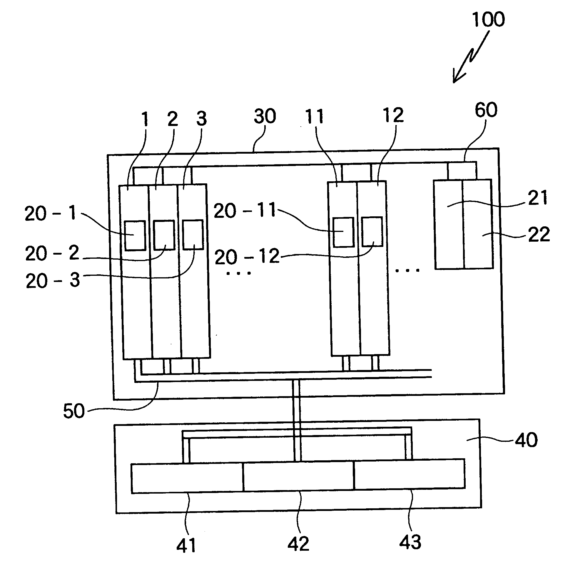
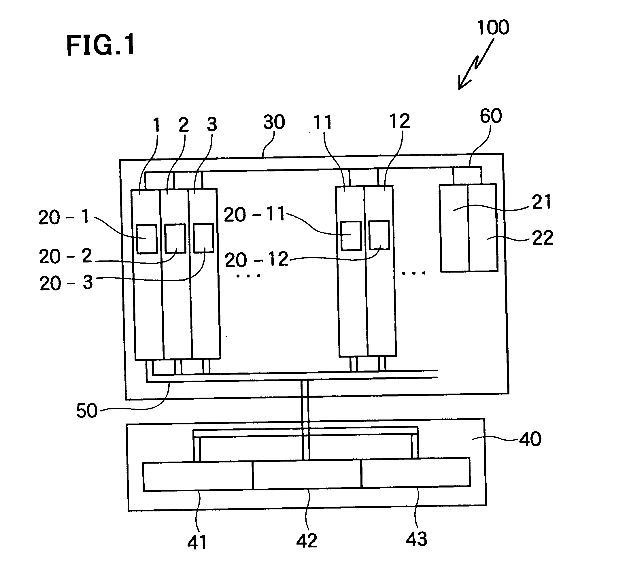
[0044]FIG. 1 is a schematic view of a cluster system 100 in accordance with the first embodiment of the present invention.

[0045] As illustrated in FIG. 1, the cluster system 100 is comprised of a plurality of CPU blade servers 1, 2, 3, - - - , 11, 12, - - - , base management controllers (BMCs) 20-1, 20-2, 20-3, - - - , 20-11, 20-12, - - - equipped in the CPU blade servers 1, 2, 3, - - - , 11, 12, - - - , first and second chassis management modules (CMMs) 21 and 22 controlling operation of the CPU blade servers 1, 2, 3, - - - , 11, 12, - - - and the base management controllers 20-1, 20-2, 20-3, - - - , 20-11, 20-12, - - - , a blade server chassis 30 accommodating therein the CPU blade servers 1, 2, 3, - - - , 11, 12, - - - and the first and second chassis management modules 21 and 22, a plurality of distributed power supply modules (DPSs) 41, 42 and 43 each acting as a power-supply device, a power bay 40 accommodating the distributed power supply modules 41, 42 and ...

Example

Second Embodiment

[0095] In the above-mentioned first embodiment, the auxiliary CPU blade servers 11, 12, 13, - - - are kept in a cool stand-by condition. In contrast, in the second embodiment, if the distributed power supply modules (DPSs) 41, 42 and 43 ensure (N+1) redundancy wherein N indicates a number of the CPU blade servers used for actual operation of the cluster system 100, that is, if there is at least one distributed power supply module which does not supply electrical power to the N CPU blade servers when electrical power is supplied to all of the N CPU blade servers, at least one of the auxiliary CPU blade servers 11, 12, 13, - - - is kept in a hot stand-by condition.

[0096] In the second embodiment, it is assumed that before there occurs a trouble in any one of the CPU blade servers 1, 2, 3, - - - used for actual operation of the cluster system 100, the distributed power supply modules (DPSs) 41 and 42 supply electrical power to the CPU blade servers 1, 2, 3, - - - .

[...

Example

Third Embodiment

[0102] In the third embodiment, each of the first and second chassis management modules 21 and 22 is designed to select a first power-supply way in which the auxiliary CPU blade servers 11, 12, 13, - - - are kept in a cool stand-by condition or a second power-supply way in which the auxiliary CPU blade servers 11, 12, 13, - - - are kept in a hot stand-by condition.

[0103] In order for the first and second chassis management modules 21 and 22 to be able to select the first or second power-supply way, each of the first and second chassis management modules 21 and 22 is designed to be able to check whether the distributed power supply modules (DPSs) 41, 42 and 43 construct (N+1) redundancy wherein N indicates a number of the CPU blade servers used for actual operation of the cluster system 100.

[0104] Specifically, the chassis management module in operation (for instance, the first chassis management module 21) judges whether there is at least one distributed power sup...


PUM


Abstract

A cluster system includes a plurality of blade servers including at least one auxiliary blade server, the rest of the blade servers being used for actual operation of the cluster system, a power-supply unit supplying electrical power to each of the blade servers, a power-supply controller which controls on/off in supplying electrical power to each of the blade servers from the power-supply unit, and a blade server monitoring unit which monitors whether there occurs any trouble in each of the blade servers. The power-supply controller, when the blade server monitoring unit finds a trouble in any one of the blade servers, stops power-supply to a blade server in which the trouble was found, and turns the auxiliary blade server into a blade server to be used for actual operation of the cluster system, in place of the blade server in which the blade server monitoring unit found a trouble.

Description

BACKGROUND OF THE INVENTION [0001] 1. Field of the Invention [0002] The invention relates to a cluster system including a plurality of blade servers, a method of controlling on / off in power-supply to a plurality of blade servers in a cluster system, and a program for causing a computer to cause the method. [0003] 2. Description of the Related Art [0004] For instance, Japanese Patent Application Publication No. 2004-110791 has suggested a cluster system including a plurality of blade servers used for actual operation of the cluster system, and an administration server which monitors performance of each of the blade servers. [0005] When the administration server finds that any one of the blade servers stalls, the administration server turns an auxiliary blade into a blade server to be used for actual operation of the cluster system, in place of the blade server in stall, keeping supplying electrical power to the blade system in stall. [0006] Since an auxiliary blade server is turned i...

Claims


Application Information

Patent Timeline
IPC IPC(8): G06F1/00
CPCG06F11/2015G06F11/2038G06F11/2028
Inventor TANAKA, YOSHIMASA
Owner NEC CORP
Why Eureka
Try Eureka