Dynamic emergency radiation monitor

a radiation monitor and dynamic technology, applied in the direction of optical radiation measurement, instruments, x/gamma/cosmic radiation measurement, etc., can solve the problems of not being able to process the detected radiation data in a convenient or desirable form, not being able to remember the significance of the various radiation units, and not being able to predict the radiation level to be encountered

Inactive Publication Date: 2006-10-26
BUSHBERG JERROLD T
View PDF7 Cites 37 Cited by
  • Summary
  • Abstract
  • Description
  • Claims
  • Application Information

AI Technical Summary

Benefits of technology

[0016] An aspect of the invention is a personal radiation monitor having a detector configured for producing real time radiation exposure data, and a processor responsive to the detector and configured for calculating one or more characteristics of an individual's radiation exposure. The processor is configured to continuously recalculate said radiation exposure data to update the radiation exposure charac

Problems solved by technology

In other situations such as in the case of a radiation leak which requires clean-up operations, or nuclear or dirty bomb detonation, the radiation levels to be encountered are not easily predicted, and these levels would likely be much higher than those encountered in the more normal situation.
The

Method used


Image

  • Dynamic emergency radiation monitor
  • Dynamic emergency radiation monitor
  • Dynamic emergency radiation monitor

Examples


Embodiment Construction

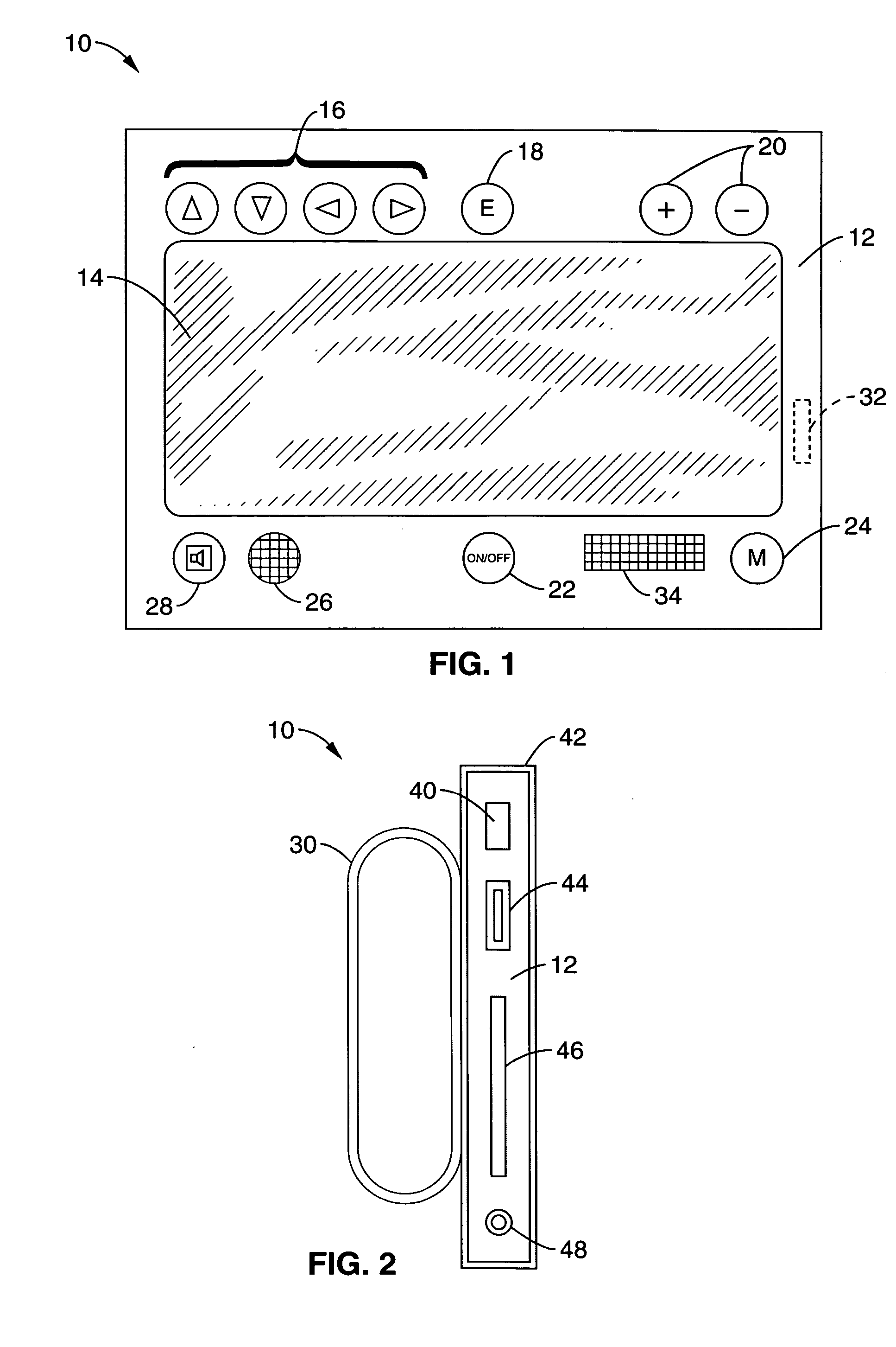
[0049] Referring more specifically to the drawings, for illustrative purposes the present invention is embodied in the apparatus generally shown in FIG. 1 through FIG. 13. It will be appreciated that the apparatus may vary as to configuration and as to details of the parts, and that the method may vary as to the specific steps and sequence, without departing from the basic concepts as disclosed herein.

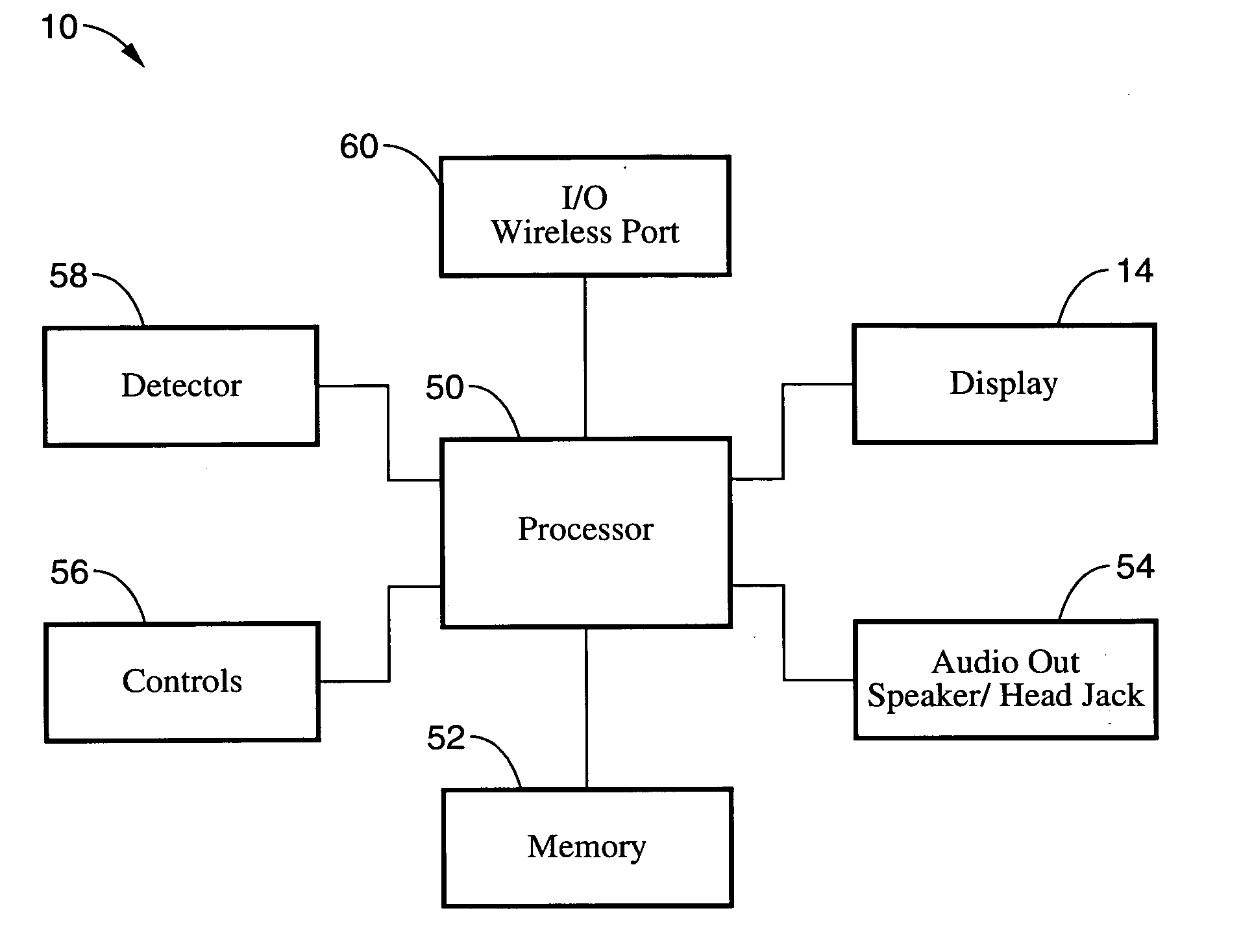
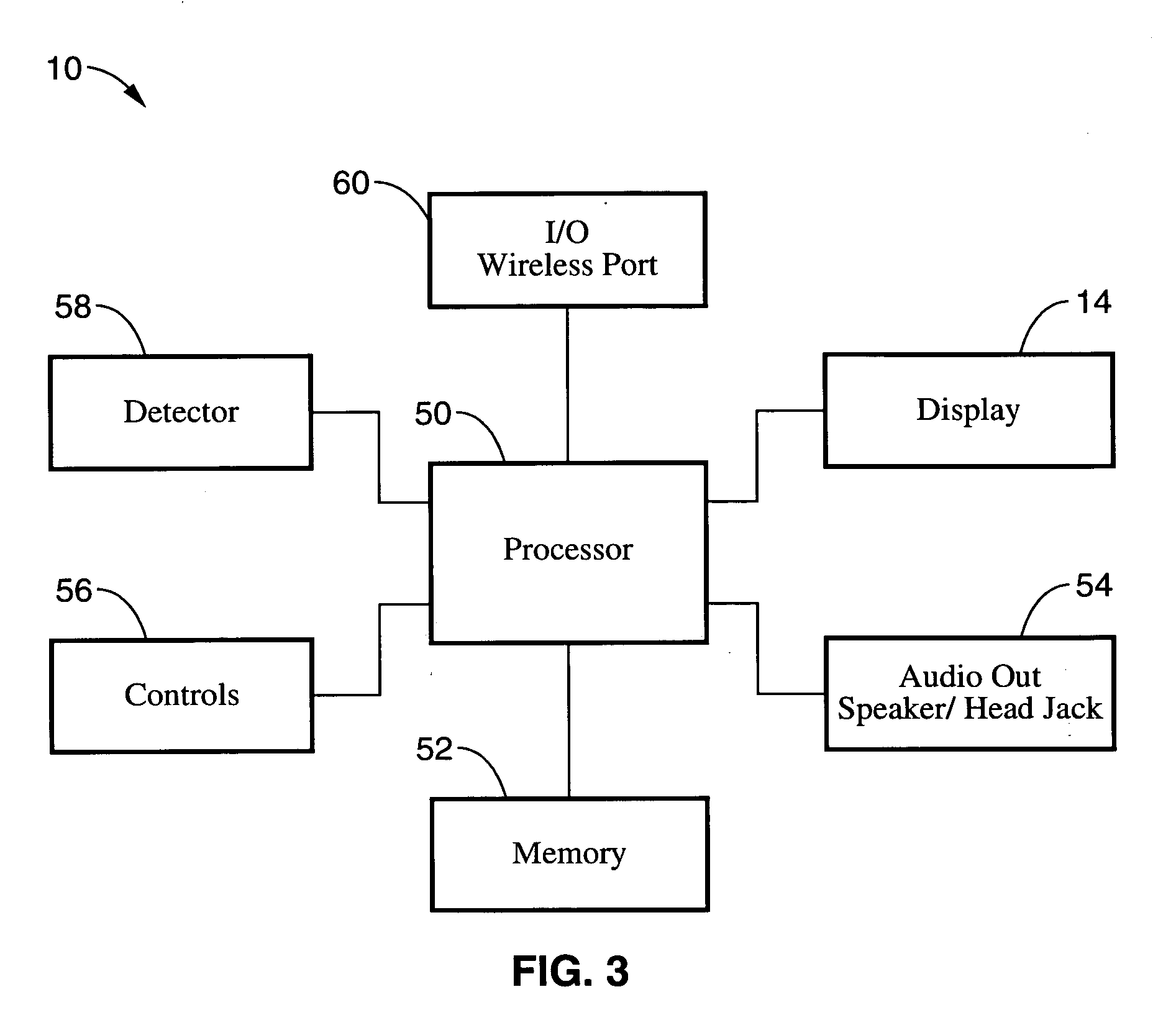
[0050] The present invention pertains to a dynamic radiation monitor / dosimeter having a detector coupled to a computer / processor to determine, at any given location, the amount of time a person has before a pre-selected maximum permissible radiation exposure is received. In general terms, the monitor dynamically calculates and outputs the user's permissible stay time for a given area based on a personalized maximum permissible dose, and adjusts in real time the output based on changes in exposure rate at any given location, accumulated dose, and elapsed time. The monitor also provides...


PUM


Abstract

A dynamic radiation monitor having a detector coupled to a computer to determine at any given location, the amount of time a person has before a pre-selected maximum permissible radiation exposure is received. The device dynamically calculates and outputs the user's permissible stay time for a given area based on a personalized maximum permissible dose, and adjusts in real time the output based on elapsed time and changing exposure rate. The device also provides the user audio and visual feedback such as varying background colors for different stay time ranges.

Description

CROSS-REFERENCE TO RELATED APPLICATIONS [0001] This application claims priority from U.S. provisional application Ser. No. 60 / 652,168 filed on Feb. 10, 2005, incorporated herein by reference in its entirety.STATEMENT REGARDING FEDERALLY SPONSORED RESEARCH OR DEVELOPMENT [0002] Not Applicable INCORPORATION-BY-REFERENCE OF MATERIAL SUBMITTED ON A COMPACT DISC [0003] Not Applicable NOTICE OF MATERIAL SUBJECT TO COPYRIGHT PROTECTION [0004] A portion of the material in this patent document is subject to copyright protection under the copyright laws of the United States and of other countries. The owner of the copyright rights has no objection to the facsimile reproduction by anyone of the patent document or the patent disclosure, as it appears in the United States Patent and Trademark Office publicly available file or records, but otherwise reserves all copyright rights whatsoever. The copyright owner does not hereby waive any of its rights to have this patent document maintained in secr...

Claims


Application Information

Patent Timeline
IPC IPC(8): G01T1/00
CPCG01T7/00G01T1/02
Inventor BUSHBERG, JERROLD T.
Owner BUSHBERG JERROLD T
Why Eureka
Try Eureka