Driving mechanism

Inactive Publication Date: 2006-10-26
FUJI PHOTO OPTICAL CO LTD
View PDF30 Cites 14 Cited by
  • Summary
  • Abstract
  • Description
  • Claims
  • Application Information

AI Technical Summary

Benefits of technology

[0017] According to the third aspect of the invention, the weight member greater in mass than the driving member is provided, thereby making it possible to transmit efficiently the elongation and contraction of the electro-mechanical conversion element to the driving member side.
[0018] According to the fourth aspect of the invention, there is provided a driving mechanism as set forth in any of the first to third aspect of the invention, wherein the weight member is a resonance frequency-reducing member. For example, as shown in FIG. 17A and FIG. 17B, there is a case where a driving force generated by the elongation and contraction of a piezoelectric element 1 is not accurately transmitted to a driven member 3 due to the eff

Problems solved by technology

However, beryllium is a rare metal and disadvantageou

Method used


Image

  • Driving mechanism
  • Driving mechanism
  • Driving mechanism

Examples


first embodiment

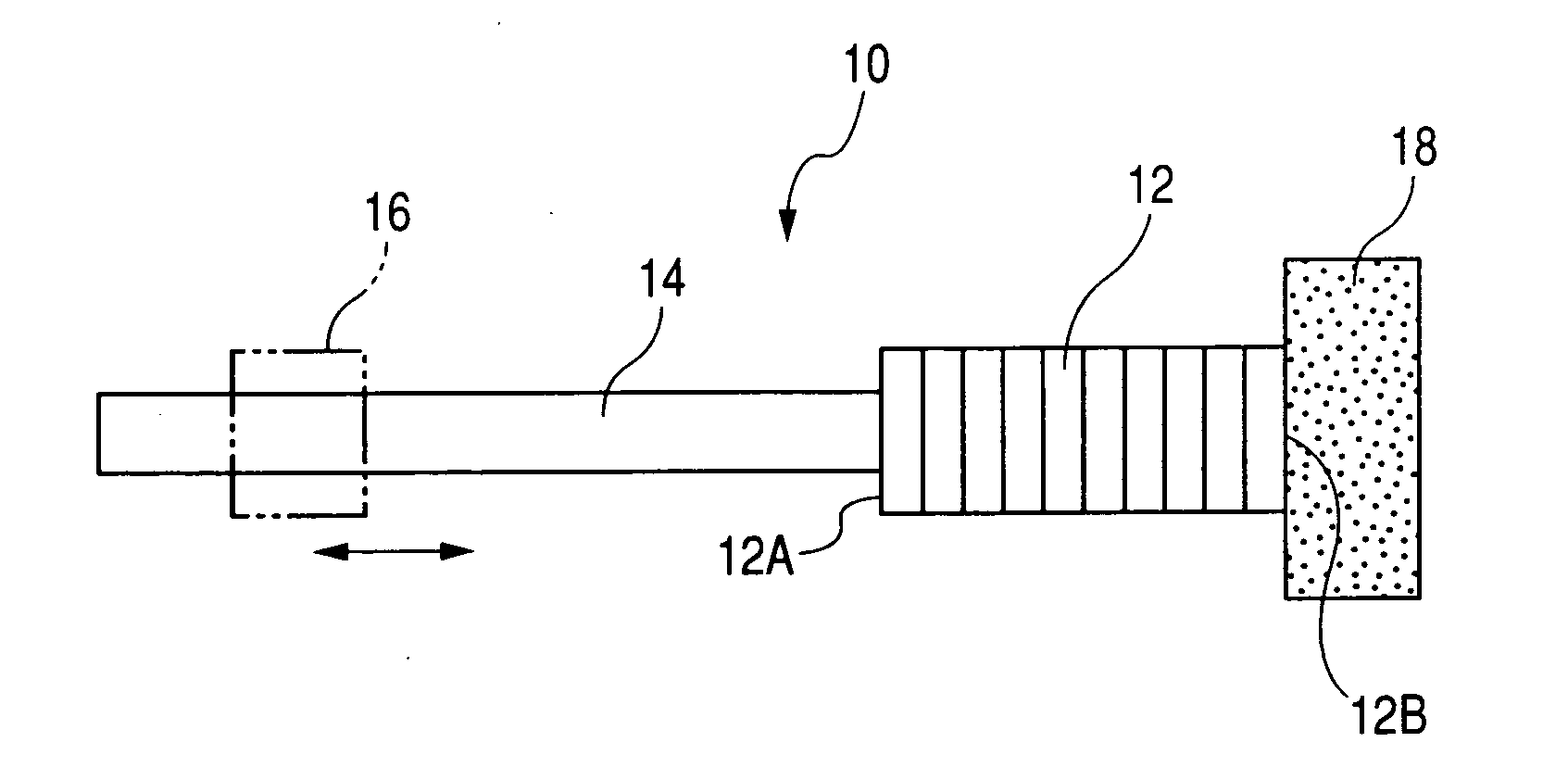
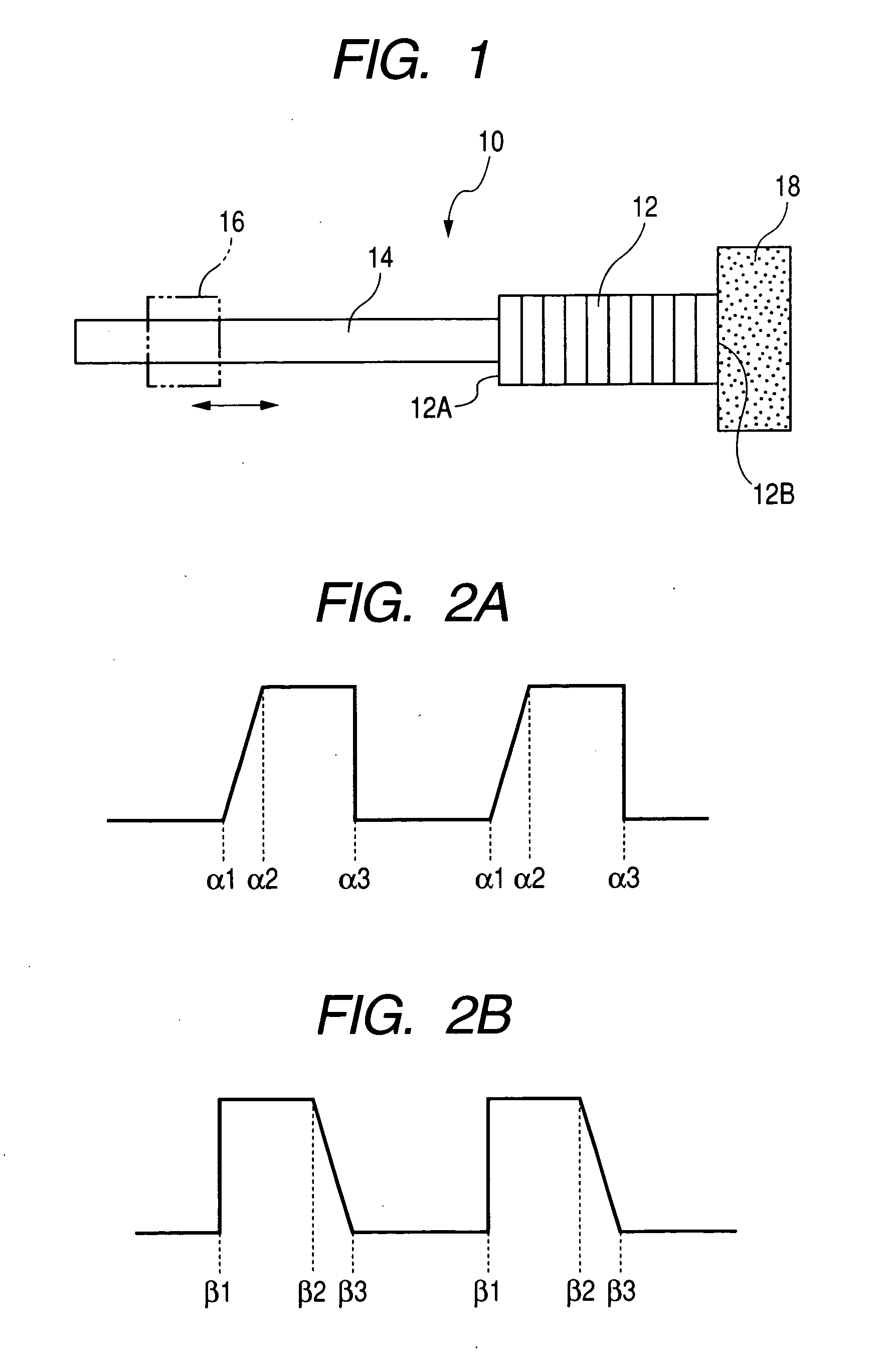
[0046]FIG. 1 is a plan view showing an actuator 10 of a driving mechanism 100 of a first embodiment in the present invention. As shown in FIG. 1, the actuator 10 is constituted by a piezoelectric element (corresponding to an electromechanical conversion element) 12, a driving member 14 and a weight member 18. The piezoelectric element 12 is laminated in the direction shown by the arrow and constituted so as to deform in a laminated direction (elongation and contraction) on application of voltage. Therefore, the piezoelectric element 12 is designed so that longer end surfaces 12A and 12B are displaced.

[0047] Of the end surfaces 12A and 12B of the piezoelectric element 12, to one end surface 12A is fastened the base end of a driving member 14. The driving member 14 is formed, for example, in a cylindrical shape, and its axis is arranged in the direction shown by the arrow (namely, in the elongating and contracting direction of the piezoelectric element). The driving member 14 is made ...

third embodiment

[0087] Next, an explanation will be made for a driving mechanism 300 of a third embodiment in the present invention with reference to FIG. 9.

[0088] As shown in FIG. 9, the driving mechanism 300 is different from the driving mechanism 200 in that a weight member 332 constituted by an elastic body such as rubber is adhered and fixed to the end surface 12B on the rear side of a piezoelectric element 12 and a surface opposite the piezoelectric element 12 in the weight member 332 is adhered and fixed to a body 20. The thus constituted mechanism is also able to provide effects and actions similar to those of the above embodiment.

fourth embodiment

[0089] Next, an explanation will be made for a driving mechanism 400 of a fourth embodiment in the present invention with reference to FIG. 10.

[0090] As shown in FIG. 10, the driving mechanism 400 is different from the driving mechanism 200 in that a weight member 418 made with a soft material is shaped into a thin plate form having a larger surface than the end surface 12B of a piezoelectric element 12, the piezoelectric element 12 is adhered and fixed at the center of the weight member 418, and both ends of the weight member 418 are adhered and fixed to a body 20. Also in the thus constituted present embodiment, since the driving member 14 is made with carbon graphite, it is possible to provide an effect similar to that of the above embodiment, namely, an accurate and stable movement of the driven member. Further, according to the thus constituted driving mechanism of the present embodiment, since the end surface 12B at the rear end of the piezoelectric element 12 is supported to ...


PUM


Abstract

A driving mechanism comprises: (i) an actuator comprising: an electro-mechanical conversion element; and a driving member which moves according to the elongation or contraction of the electro-mechanical conversion element; and (ii) a driven member frictionally engaged with the driving member, wherein the actuator which allows the driven member to move along the driving member, and the driving member is a graphite composite.

Description

BACKGROUND OF THE INVENTION [0001] 1. Field of the Invention [0002] The present invention relates to a driving mechanism, a photographic mechanism in which an optical member is connected to the driving mechanism such as a small digital camera and a web camera and a cellular phone equipped with the driving mechanism and the photographic mechanism. [0003] 2. Description of the Related Art [0004] An actuator in which an electro-mechanical conversion element such as a piezoelectric element is used is known as a driving mechanism for a lens used in digital cameras and the like. For example, as shown in the embodiments of Japanese Patent No. 3171187 or Japanese Patent No. 3180557, the actuator is, in general, constituted by an electromechanical conversion element and a driving member and fixed to a cabinet (or support member) on one end surface of the electromechanical conversion element in the elongation and contraction direction. A driving member is fastened to the other end surface of ...

Claims


Application Information

Patent Timeline
IPC IPC(8): H01L41/00H02N2/00
CPCH02N2/025G02B7/023H01L21/67742H01L21/67766
Inventor MANABE, MITSUO
Owner FUJI PHOTO OPTICAL CO LTD
Why Eureka
Try Eureka