Plasma display module

a technology of display module and plasma, which is applied in the direction of circuit bendability/stretchability, identification means, instruments, etc., can solve problems such as metal fatigue, and achieve the effect of preventing metal fatigue of wiring and reducing stress

Inactive Publication Date: 2006-10-26
HITACHI LTD
View PDF5 Cites 8 Cited by
  • Summary
  • Abstract
  • Description
  • Claims
  • Application Information

AI Technical Summary

Benefits of technology

[0010] An object of the present invention is to prevent the metal fatigue of the wirings by means of strengthening the flexible substrate and providing a mounting structure capable of alleviating the stress.

Problems solved by technology

In particular, the wiring disposed on the outer side in the width direction of the flexible substrate suffers more repetitive stress near the edge portion of the metal plate, and there is the possibility that the metal fatigue occurs.

Method used


Image

  • Plasma display module
  • Plasma display module
  • Plasma display module

Examples


Embodiment Construction

[0024] Hereinafter, embodiments of the present invention will be described in detail with reference to the accompanying drawings. Note that components having the same function are denoted by the same reference symbols throughout the drawings for describing the embodiment, and the repetitive description thereof will be omitted. FIG. 1 to FIG. 8 are explanatory drawings of the PDP module of the present embodiment.

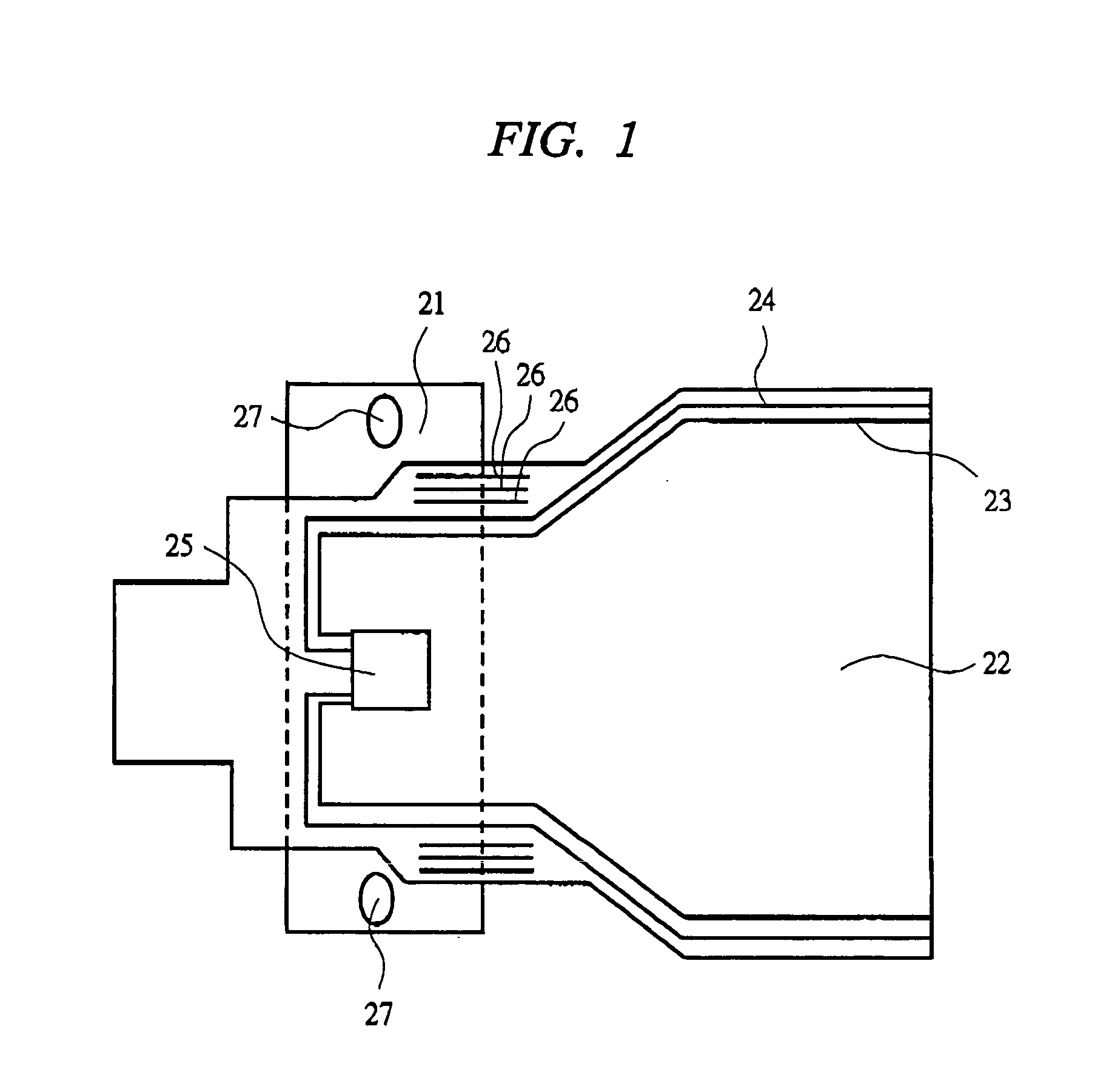
[0025]FIG. 1 shows a structure of a driver module 7 in the PDP module according to the present embodiment. The driver module 7 includes a metal plate 21 serving as a heat radiating member, a flexible substrate 22 having wirings connected to electrodes of a panel, and others. Further, wirings 26 which are not connected to the electrodes of a panel are provided on both edges in a width direction of the flexible substrate 22 and on the outer sides of signal wirings 23 and ground lines 24. The wirings 26 are formed of a plurality of individually separated linear patterns. The me...


PUM

PropertyMeasurementUnit
glass transition temperatureaaaaaaaaaa
widthaaaaaaaaaa
flexibleaaaaaaaaaa

Abstract

In a plasma display module, a flexible substrate is strengthened and a mounting structure for alleviating stresses is provided, thereby preventing the metal fatigue of wirings. In a PDP (Plasma Display Panel) module, a metal plate and a flexible substrate constituting a driver module are provided. On the flexible substrate, wirings not connected to electrodes of the panel (independent linear patterns) are disposed on an outer side of wirings and near an edge portion of the metal plate to which the flexible substrate is attached.

Description

CROSS-REFERENCE TO RELATED APPLICATION [0001] The present application claims priority from Japanese Patent Application No. JP 2005-12316S filed on Apr. 21, 2005, the content of which is hereby incorporated by reference into this application.TECHNICAL FIELD OF THE INVENTION [0002] The present invention relates to a plasma display module (PDP module). More particularly, it relates to a flexible substrate of the PDP module and a mounting structure of the flexible substrate. BACKGROUND OF THE INVENTION [0003] In general, in a plasma display panel (PDP), discharge gas is filled in spaces between opposing glass substrates. In this structure, discharges are generated by electrodes disposed in a matrix form, and phosphors of the cells separated by barrier ribs are excited by the discharges to emit light. A drive circuit which applies voltages to each electrode is disposed on a rear side of the PDP, and the PDP is electrically connected to the drive circuit via a flexible substrate. An examp...

Claims


Application Information

Patent Timeline
Patent Type & Authority Applications(United States)
IPC IPC(8): G02F1/1345G09F9/00
CPCH05K1/0281H05K3/0061H05K2201/2009H05K2201/09781H05K3/361H01J11/34H01J11/46H01J17/28
Inventor KAWAMURA, TOMOYUKIOHNO, TAIZOOKADA, YOSHINORISASAKI, TAKASHIISOHATA, HIDEKIISHIWATA, KENJI
Owner HITACHI LTD
Why Eureka
Try Eureka