Disaster recovery method, disaster recovery system, remote copy method and storage system

a disaster recovery and remote copy technology, applied in the field of disaster recovery technology through log transfer, can solve the problems of inability to quickly restart the service, inability to ensure the consistency of read content, and long time-consuming fo, so as to prevent the conflict between log reading and writing through the remote copy operation

Active Publication Date: 2006-10-26
HITACHI LTD
View PDF16 Cites 14 Cited by
  • Summary
  • Abstract
  • Description
  • Claims
  • Application Information

AI Technical Summary

Benefits of technology

[0034] (3) In the method of using the reading in cooperation with remote copy operation, when the logs are applied in the sub-site, the following processes are performed. That is, the second copy operation is interrupted; the log blocks are read from the second volume; the read log blocks are applied; and the log application process is interrupted and then the second copy operation is restarted when there are no logs to be read. By doing so, the second copy

Problems solved by technology

The reason is that the consistency of the read content cannot be assured if the VOL being written through the remote copy oper

Method used


Image

  • Disaster recovery method, disaster recovery system, remote copy method and storage system
  • Disaster recovery method, disaster recovery system, remote copy method and storage system
  • Disaster recovery method, disaster recovery system, remote copy method and storage system

Examples


first embodiment

[0060] The DR system according to the present invention will be described with reference to FIG. 1 to FIG. 6.

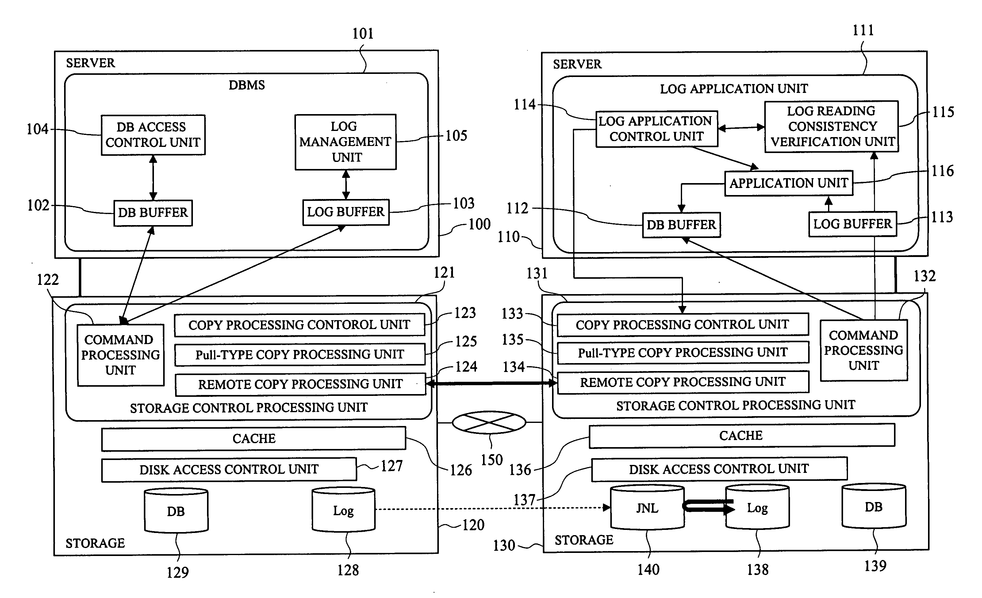
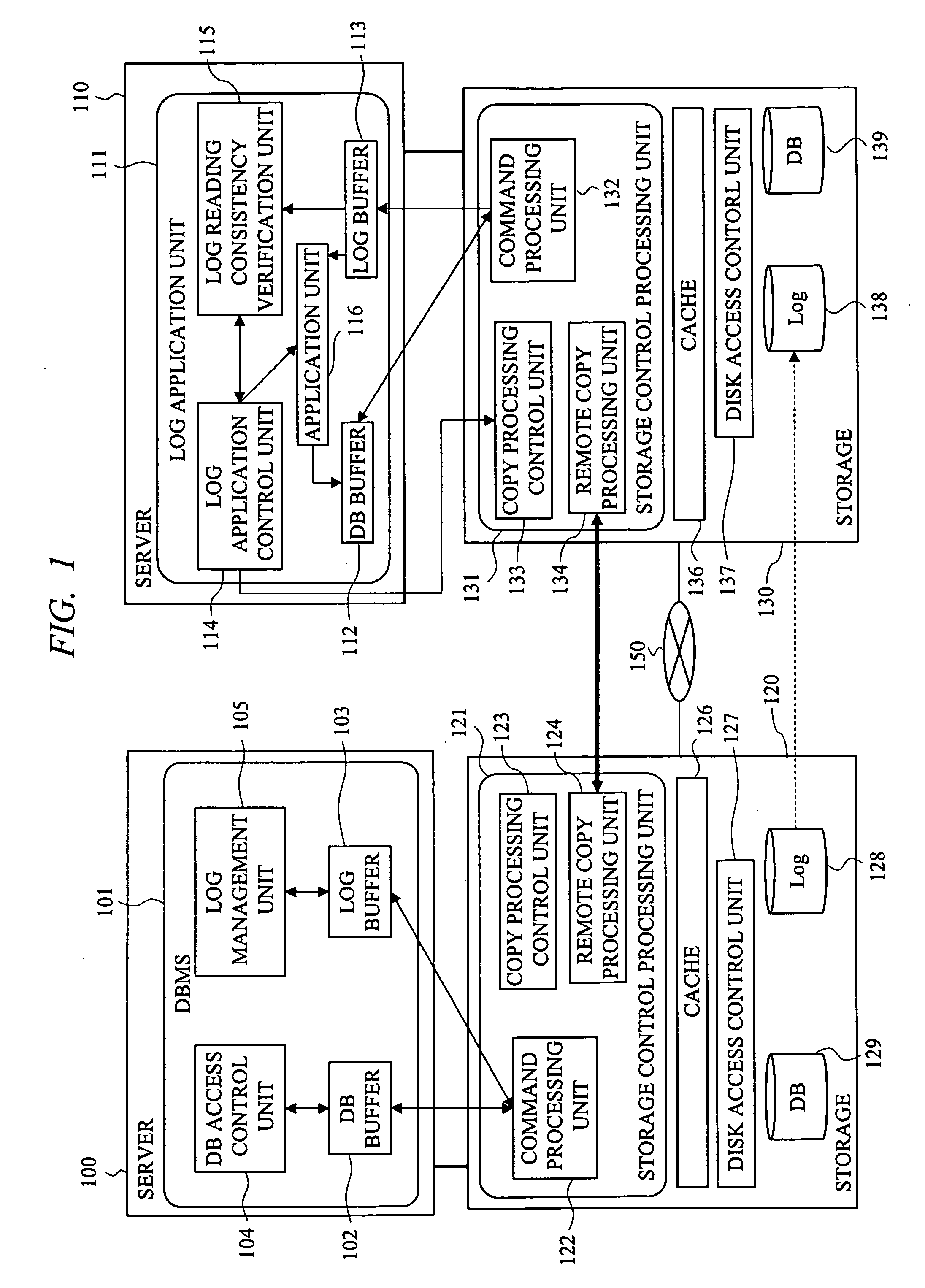
[0061] Firstly, an example of the configuration of the DR system according to this embodiment will be described with reference to FIG. 1. FIG. 1 is a diagram showing an example of the configuration of the DR system.

[0062] The DR system according to this embodiment employs a method in which logs are reread and is composed of a main site and a sub-site. The main site comprises a server 100 including a computer on which a DBMS is operated and a storage 120 to store the log file and the DB file of the DBMS. The sub-site comprises a server 110 including a computer on which a sub-DBMS to perform log application process or a function specialized to apply logs (log application function) is operated and a storage 130. The storage 120 of the main site and the storage 130 of the sub-site are connected through a network 150.

[0063] A DBMS 101 is operated in the server 100 of the main si...

second embodiment

[0095] The DR system according to the present invention will be described with reference to FIG. 7 to FIG. 13.

[0096] Firstly, an example of the configuration of the DR system according to this embodiment will be described with reference to FIG. 7. FIG. 7 is a diagram showing an example of the configuration of the DR system.

[0097] The DR system according to this embodiment adopts a method of using the log reading in cooperation with a remote copy operation. For example, when the reading process and the writing process conflict, the log is read incorrectly. Therefore, in the method of using the log reading in cooperation with the remote copy operation as described in this embodiment, the writing process through the remote copy operation is forbidden when the reading process is performed by the log application function. By doing so, the conflict between the reading process and the writing process can be prevented.

[0098] Comparing with the first embodiment, a Pull-type copy processing...

third embodiment

[0120] The DR system according to the present invention will be described with reference to FIG. 14.

[0121] An example of the configuration of the DR system according to this embodiment will be described with reference to FIG. 14. FIG. 14 is a diagram showing an example of the configuration of the DR system.

[0122] The DR system according to this embodiment comprises a main site, a sub-site and a relay site to relay between the main site and the sub-site. A server 100 and a storage 120 of the main site and a server 110 and a storage 130 of the sub-site are the same as those shown in FIG. 1 of the first embodiment or FIG. 7 of the second embodiment. The relay site is formed of a storage 1300, and the storage 1300 includes a storage control processing unit 1301, a log VOL 1302, and a JNL VOL 1303.

[0123] The storage 120 of the main site and the storage 1300 of the relay site are connected through a network 1304, and the storage 1300 of the relay site and the storage 130 of the sub-site...


PUM


Abstract

A disaster recovery technology capable of achieving the high-speed FO and correctly reading the logs even if the unit of logs written in the main site is large is provided. In the disaster recovery system comprising a main site and a sub-site, when the writing in units of a log block consisting of a plurality of log records is performed in the main site and the logs are applied in the sub-site, the log blocks are read from the sub-storage to verify the consistency, and it is determined whether the reading process conflicts with the writing process through the remote copy operation when reading the logs. Then, only the log blocks in which the reading process does not conflict with the writing process as a result of the determination are applied to the database. Thereby, the logs are applied in the sub-site independently to recover the database.

Description

CROSS-REFERENCE TO RELATED APPLICATION [0001] The present application claims priority from Japanese Patent Application No. JP2005-121805 filed on Apr. 20, 2005, the content of which is hereby incorporated by reference into this application. [0002] The present application is related to U.S. application Ser. No. 10 / 989398, filed on Nov. 17, 2004, titled “Disaster Recovery System Suitable for Database System” and U.S. application Ser. No. 11 / 012,102, filed on Dec. 16, 2004, titled “Method and Program for Creating Backup Data in A Database Backup System”. Technical Field of the Invention [0003] The present invention relates to a disaster recovery technology by means of a log transfer. More specifically, the present invention relates to the technology effectively applied to a disaster recovery technology in which logs are read and applied in units finer than a file and the log rereading or the reading in cooperation with a remote copy operation is used in the log reading and application ...

Claims


Application Information

Patent Timeline
IPC IPC(8): G06F12/16
CPCG06F11/2097G06F11/1402
Inventor SUZUKI, YOSHIOKAWAMURA, NOBUOYAMAGUCHI, KOTAFUJIWARA, SHINJIWATANABE, SATORU
Owner HITACHI LTD
Why Eureka
Try Eureka