Storage system and data management method

a storage system and data management technology, applied in the field of storage system and data management method, can solve the problems of deteriorating responsiveness, overloaded processing load for backup processing in the storage device and capacity load, and still major problems, so as to prevent the overload of the memory capacity the processing load and the capacity load of the first storage devi

Inactive Publication Date: 2006-10-26
HITACHI LTD
View PDF7 Cites 119 Cited by
  • Summary
  • Abstract
  • Description
  • Claims
  • Application Information

AI Technical Summary

Benefits of technology

[0015] As a result, this storage system is able to effectively prevent the overload of the memory capacity of the first storage device caused by the first storage device retaining backup data, while rebuilding the first volume without imposing burden on the first storage device. Accordingly, the processing load and capacity load of the first storage device, which is the main storage device, can be considerably reduced in relation to the backup processing and volume rebuilding processing.

Problems solved by technology

Thus, with a conventional storage system, the processing load for performing backup processing in the storage device and the capacity load for storing the backup data were significant, and there were problems in that the backup processing and data I / O request from the host computer would compete and deteriorate the responsiveness to such data I / O request, and the memory capacity for storing data from the host computer would be become overloaded.
Even with the method disclosed in foregoing Japanese Patent Laid-Open Publication No. 2005-18738, the processing load for performing backup processing in the storage device and the capacity load are still major problems, and it cannot be said that this provides a sufficient solution for overcoming these problems.
Further, although Japanese Patent Laid-Open Publication No. 2003-233518 discloses the provision of a secondary volume to a sub storage device in addition to providing a primary volume to a main storage device, if the secondary volume is copied as is, this will cause problems of the transfer load between the sub storage device and the main storage device to receive data from the host computer becoming significant, and the processing load of the main storage device becoming significant, and thereby deteriorate the responsiveness to the host computer.

Method used


Image

  • Storage system and data management method
  • Storage system and data management method
  • Storage system and data management method

Examples


first embodiment

(1) First Embodiment

(1-1) Configuration of Storage System in Present Embodiment

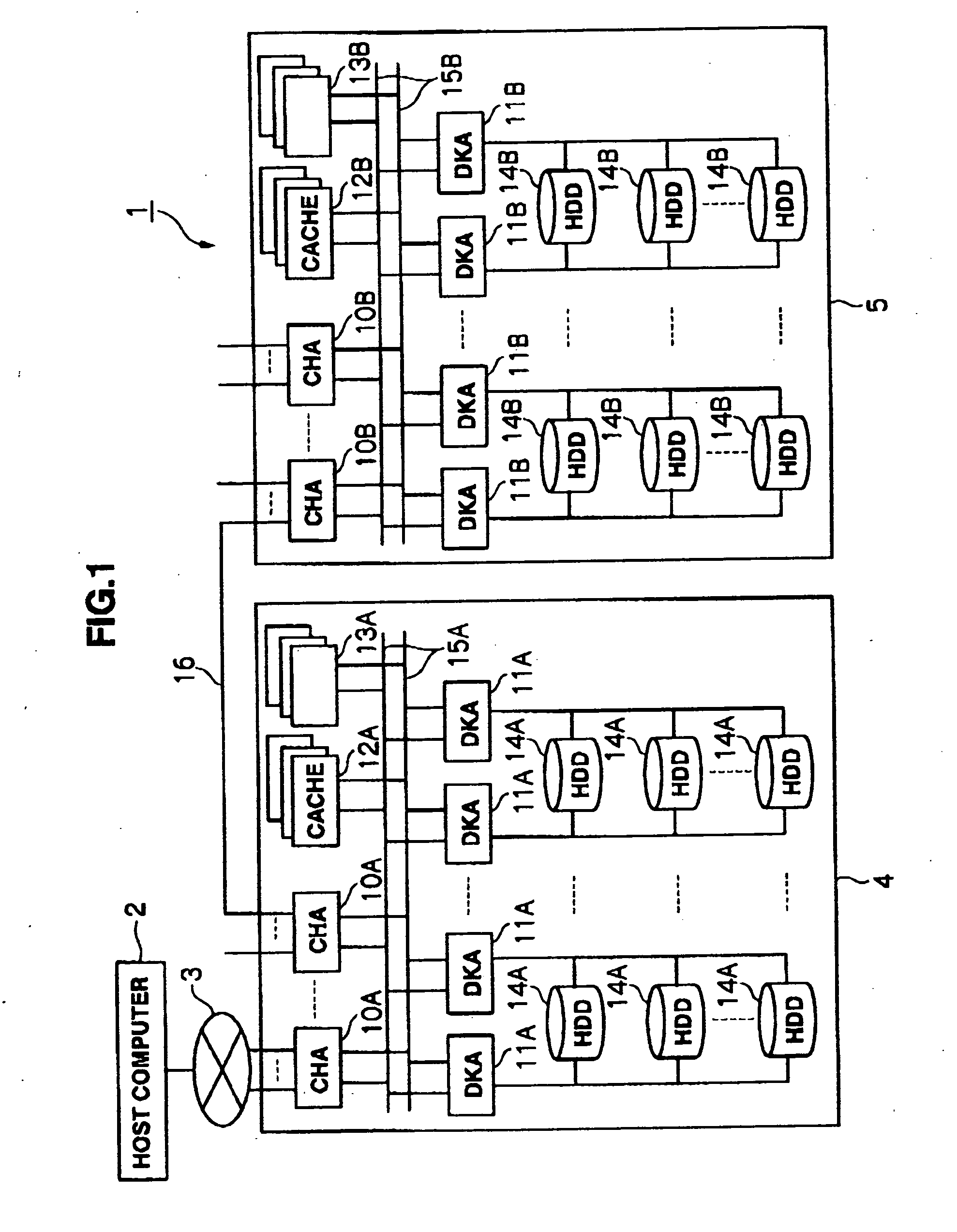
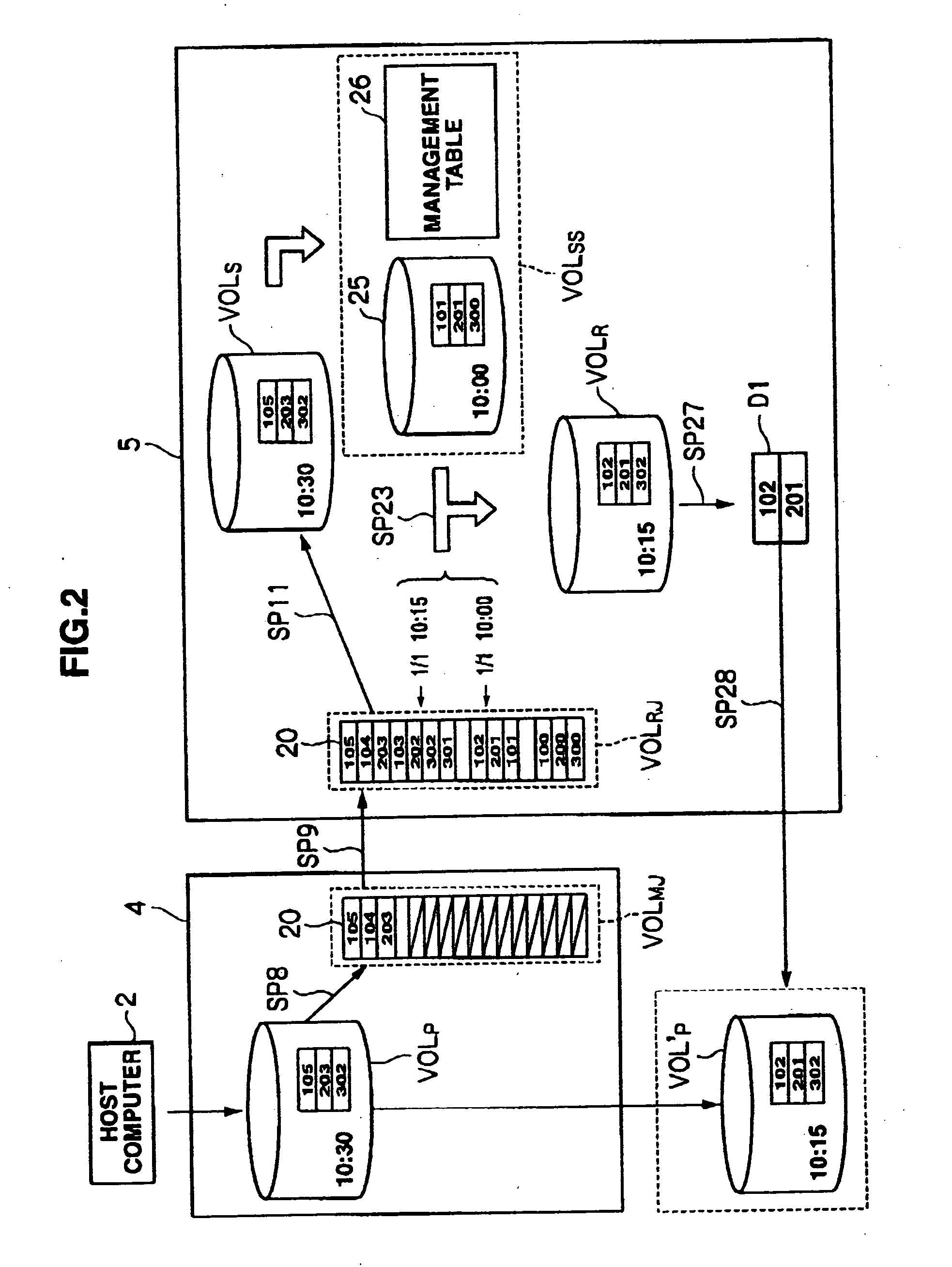
[0037]FIG. 1 is a diagram showing a storage system 1 of the present embodiment. The storage system 1 is configured by a host computer 2 being connected to a first storage device (this is hereinafter referred to as a “first DKC”) 4 via a network 3, and a second storage device (this is hereinafter referred to as a “second DKC”) 5 for data backup being connected to this first DKC 4.

[0038] The host computer 2 is a computer equipped with the likes of a CPU (Central Processing Unit) and memory. Various functions are realized by the CPU of the host computer 2 executing various programs. The host computer 2, for example, is constituted from the likes of a personal computer, workstation or mainframe computer.

[0039] The host computer 2 is able to perform the I / O of data to and from the first DKC 4 via the network 3. The network 3 may be constituted, for instance, from a LAN, SAN, Internet, dedicated line, public...

second embodiment

(2) Second Embodiment

[0085]FIG. 10 is a diagram showing the storage system 30 according to the second embodiment, and the components corresponding to the components illustrated in FIG. 1 are given the same reference numeral. This storage system 30 is configured similar to the storage system 1 (FIG. 1) according to the first embodiment other than that the processing contents of the primary channel adapter 33A of the first DKC 31 and the secondary channel adapter 33B of the second DKC 32 relating to the backup processing and volume rebuilding processing are different.

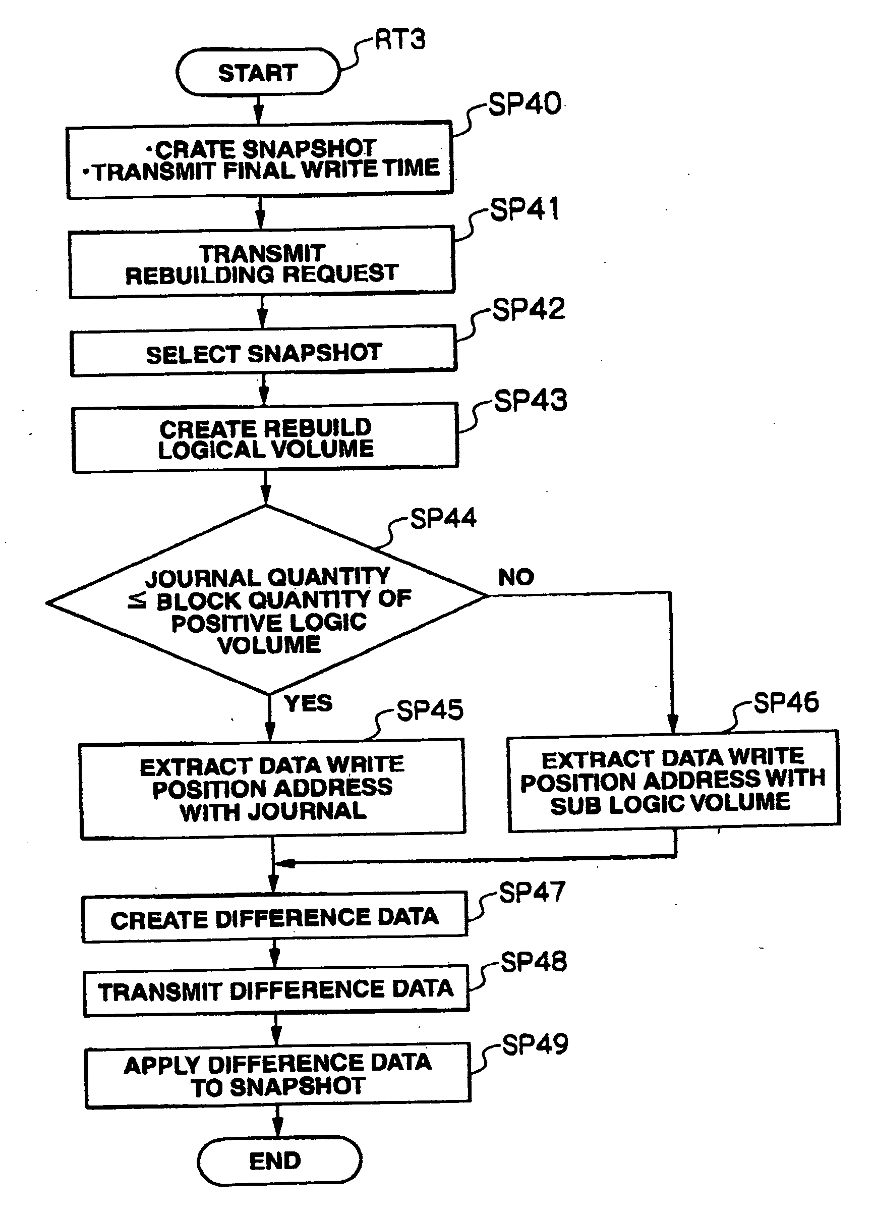
[0086] In actuality, with this storage system 30, as shown in FIG. 11, the first DKC 31, upon being provided with a rebuilding processing from the host computer 2, acquires a snapshot 34 of the primary logical volume VOLP at the point in time such rebuilding processing was provided, and thereafter acquires a snapshot 35 of the primary logical volume VOLP of the designated rebuilding time so as to apply the difference dat...

third embodiment

(3) Third Embodiment

[0094]FIG. 13 is a diagram showing the storage system 40 according to the third embodiment, and the components corresponding to the components illustrated in FIG. 1 are given the same reference numeral. This storage system 30 is configured similar to the storage system 1 (FIG. 1) according to the first embodiment other than that the user is able to freely select, as the volume rebuilding processing mode, either a first volume rebuilding processing mode for returning the primary logical volume VOLP itself to the state of the rebuilding time as described in the first embodiment, or a second volume rebuilding processing mode for acquiring the snapshot 35 (FIG. 11) of the primary logical volume VOLP as described in the second embodiment.

[0095] In actuality, with this storage system 40, the user is able to operate the host computer 41 and display the likes of a volume rebuilding processing mode setting screen 50 for setting and inputting the desired rebuilding time o...


PUM


Abstract

On the first storage device side, when data is written in a first volume, a journal of such data is transmitted to a second storage device; on the second storage device side, a snapshot of a second volume and the respective journals are stored; on the second storage device side, the first volume is rebuilt at a rebuilding time according to a rebuilding order; on the second storage device side, data of an address rewritten from the rebuilding time onward is transmitted as difference data to the first storage device; and on the first storage device side, the first volume is rebuilt at the rebuilding time based on the difference data.

Description

CROSS-REFERENCES TO RELATED APPLICATIONS [0001] This application relates to and claims priority from Japanese Patent Application No. 2005-123665, filed on Apr. 21, 2005, the entire disclosure of which is incorporated herein by reference. BACKGROUND OF THE INVENTION [0002] 1. Field of the Invention [0003] The present invention relates to a storage system and data management method and, for instance, is preferably employed in a storage system. [0004] 2. Description of the Related Art [0005] Conventionally, as a management method of stored data in a storage system, the process of backing up data stored in a volume and, when there is any failure in this volume (including the data stored in this volume), using this backup data for rebuilding the volume to the state prior to such failure is being widely used. [0006] As this kind of backup method in a storage system, conventionally, there is a method where, when data is written in a primary volume from a host computer, a so-called journal ...

Claims


Application Information

Patent Timeline
Patent Type & Authority Applications(United States)
IPC IPC(8): G06F12/16
CPCG06F11/1471G06F11/1458Y10S707/99955Y10S707/99953G06F2201/84G06F11/1456
Inventor SHONO, KAZUAKIHIRAKAWA, YUSUKEOKUMOTO, KATSUHIRO
Owner HITACHI LTD
Why Eureka
Try Eureka