Multiple computer equipment and management method thereof

a technology of computer equipment and management methods, applied in computing, power supply for data processing, instruments, etc., can solve the problems of inefficient low load ac-dc power supply modules, inefficient low load ac-dc power supply, and inefficiency of ac-dc power supply modules, so as to prevent electric power from becoming inefficient and reduce wasteful power consumption.

Inactive Publication Date: 2006-10-26
HITACHI LTD
View PDF4 Cites 29 Cited by
  • Summary
  • Abstract
  • Description
  • Claims
  • Application Information

AI Technical Summary

Benefits of technology

[0018] In multiple computer equipment, even if an operation state of computer equipment changes, it is possible to control the number of operating AC-DC power supply modules in response to a processor state and a system state. Therefore, it is possible to prevent the electric power from becoming inefficient, and thereby to reduce the wasteful power consumption.

Problems solved by technology

However, the inventor found out that when the AC-DC power supply modules included in the multiple computer equipment described above are managed, the undermentioned problems will arise.
Accordingly, if the sets of computer equipment located in the chassis are partially in a power OFF state or in a sleep state, or if a processor included in computer equipment is in the sleep state, the power consumption decreases.
Therefore, for the operation of the sets of computer equipment located in the chassis, the electric power is supplied by the AC-DC power supply modules having the excessive output power.
In general, an AC-DC power supply module inefficiently works in the low load state.
When the load is low (LL), the power supply is inefficient, that is, the wasteful power consumption is large.
Since the blade server incorporates a plurality of AC-DC power supply modules, there arises a problem of wasteful total power consumption: (the wasteful power consumption (W))×(the number of AC-DC power supply modules) (W).
However, in this method of the publicly known example, if many sets of computer equipment are suddenly brought into a power ON state, or if a system returns from a sleep state to a normal operation state, or if a-processor returns from the sleep state to the normal operation state, there is a problem in that it is not possible to cope with the sudden increase in power consumption by calculating the maximum power consumption as a result of monitoring the power consumption, and then by determining the number of required power supply units.

Method used


Image

  • Multiple computer equipment and management method thereof
  • Multiple computer equipment and management method thereof
  • Multiple computer equipment and management method thereof

Examples


Embodiment Construction

[0036] Embodiments of the present invention will be described in detail with reference to drawings below. Note that in order to illustrate the embodiments, the same parts are in principle designated by similar reference numerals in all of the drawings, and therefore, in principle the description of the parts will not be repeated.

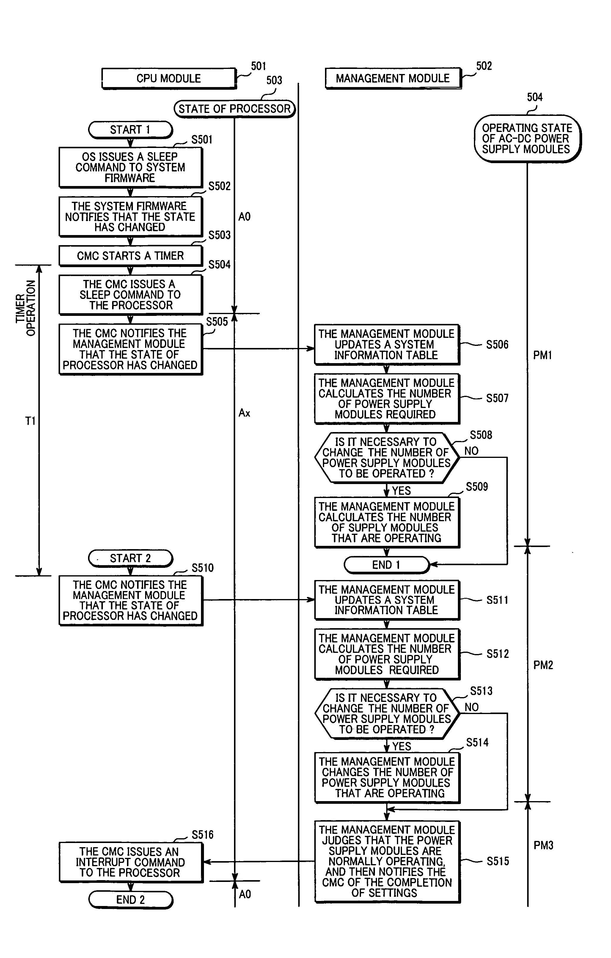
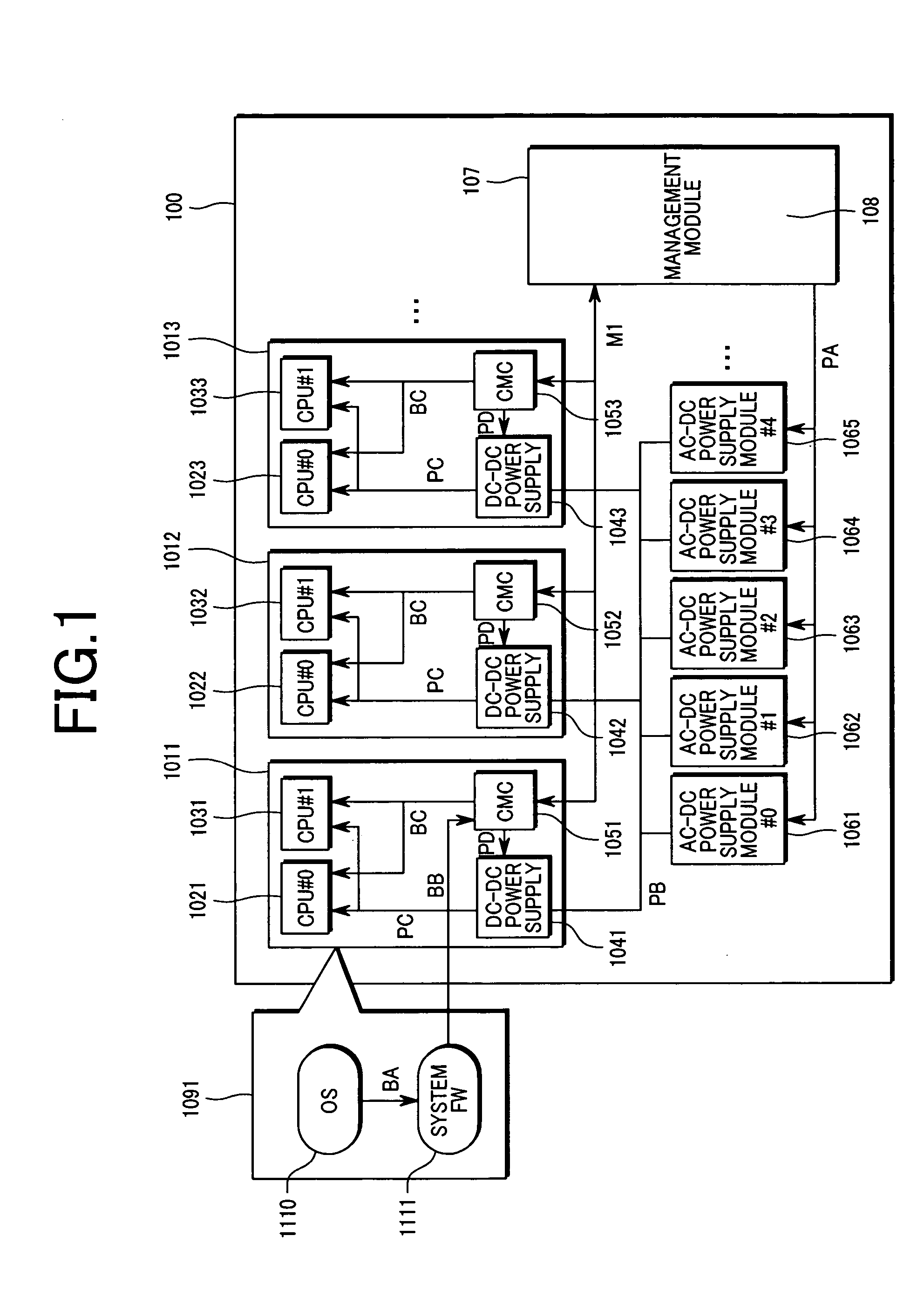
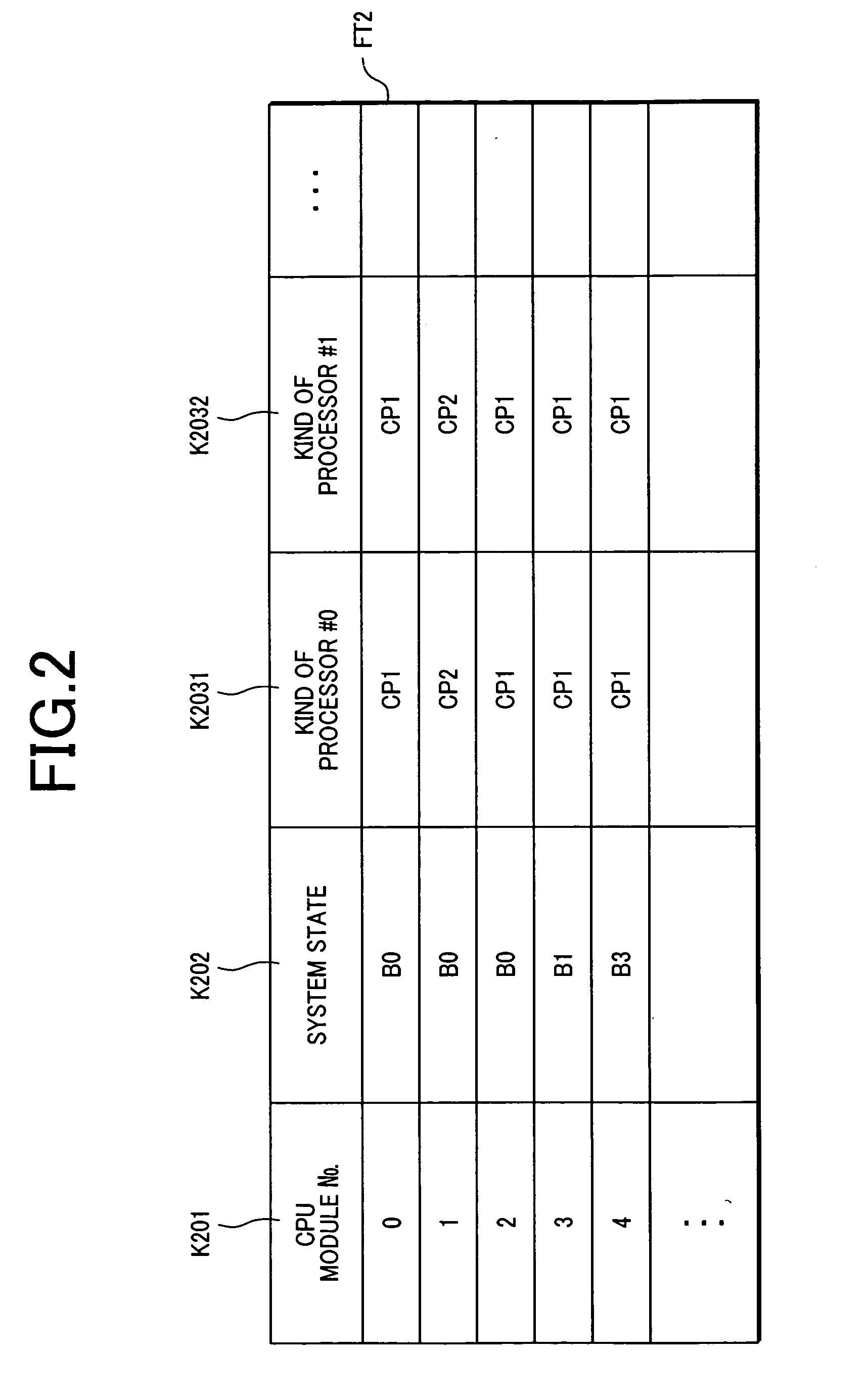
[0037] First of all, a configuration of multiple computer equipment according to one embodiment of the present invention will be described. FIG. 1 is a block diagram illustrating the multiple computer equipment according to one embodiment of the present invention. FIG. 2 is an explanatory diagram illustrating an example of CPU module operation information held by a management module installed in the multiple computer equipment shown in FIG. 1. FIG. 3 is an explanatory diagram illustrating an example of processor state information held by the management module installed in the multiple computer equipment shown in FIG. 1. FIG. 4 is an explanatory diagram illu...


PUM


Abstract

An object of the present invention is to provide a management technique for managing power supply modules. In multiple computer equipment 100, in response to a load state, if an operation system 1101 issues a command that changes a processor state of a processor 1021 to a sleep state, a management module 107 is notified through a management network MI that the processor state has changed. The management module 107 holds a system information 108, and performs the steps of: updating system information 108 because the processor state has changed; from this system information 108, calculating the power consumption required for the multiple computer equipment 100; determining the number of required AC-DC power supply modules 1061, 1062, . . . to be operated; and changing the number of operating AC-DC power supply modules 1061, 1062, . . . by use of a control interface PA.

Description

CLAIM OF PRIORITY [0001] The present application claims priority from Japanese application JP2005-124517, filed on Apr. 22, 2005, the content of which is hereby incorporated by reference into this application. BACKGROUND OF THE INVENTION [0002] 1. Field of the Invention [0003] The present invention relates to management technologies used for computer equipment, and more particularly to technologies applied effectively to control of a power supply included in multiple computer equipment, which is composed of two or more sets of computer equipment mounted in a case. [0004] 2. Description of the Related Arts [0005] A WEB server, an application server, and a database server used for an operation system of a company use computer equipment comprising a processor, a memory, an IO device, and a storage device. In recent years, multiple computer equipment has been coming into wider use in order to achieve space saving computer equipment and to place, at one location, servers included in a sy...

Claims


Application Information

Patent Timeline
Patent Type & Authority Applications(United States)
IPC IPC(8): G06F1/00
CPCG06F1/263
Inventor BABA, TAKASHIGEHORIMOTO, KAZUHIDE
Owner HITACHI LTD
Why Eureka
Try Eureka